FP2SH (Discontinued Products)
Download
-
Discontinued Products
-
Specifications
-
Dimensions
-
Software
-
Compatibility with CPU unit
-
Cautions For Use
Ⅾiscontinued
Last time buy (JST)
September 30, 2022
------------------------------ Tab1 showing ------------------------------
Discontinued Products

[Note]
The following applicable products and options are available continuously.
Intelligent units for remote I/O control
| Product name | Specifications | Controllable I/O points | Product No. | Part No. | ||
|---|---|---|---|---|---|---|
| FP I/O Terminal Board [MIL connector type] | 24 V DC input / 0.2 A Transistor output | Input: 16 points, Output: 16 points | AFP87446 | AFP87446 | ||
| FP I/O Terminal Board [Terminal block type] | 24 V DC input / 0.2 A Transistor output | Input: 16 points, Output: 16 points | AFP87444 | AFP87444 | ||
| 24 V DC input / 2 A Relay output | Input: 16 points, Output: 8 points | AFP87432 | AFP87432 | |||
| FP I/O Terminal Unit | Serves as a slave controller. Expandable up to 32 points. (Operating voltage: 24 V DC) | FP I/O Terminal Unit (basic) | Input unit 24 V DC input | Input 8 points | AFP87421 | AFP87421 |
| Input 16 points | AFP87422 | AFP87422 | ||||
| Output unit 0.5 A Transistor output | Output 8 points | AFP87423 | AFP87423 | |||
| Output 16 points | AFP87424 | AFP87424 | ||||
| FP I/O Terminal Expansion Unit | Input unit 24 V DC input | Input 8 points | AFP87425 | AFP87425 | ||
| Input 16 points | AFP87426 | AFP87426 | ||||
| Output unit 0.5 A Transistor output | Output 8 points | AFP87427 | AFP87427 | |||
| Output 16 points | AFP87428 | AFP87428 | ||||
Power supply units
| Product name | Specifications | Product No. | Part No. |
|---|---|---|---|
| FP2 Power Supply Unit | Input: 100 to 120 V AC, Output: 2.5 A | FP2-PSA1 | AFP2631 |
| Input: 200 to 240 V AC, Output: 2.5 A | FP2-PSA2 | AFP2632 | |
| Input: 100 to 240 V AC, Output: 5 A | FP2-PSA3 | AFP2633 |
Others
| Product name | Part No. | |
|---|---|---|
| Spare battery (Lithium battery) For FP2SH CPU unit, battery with cable | AFP8801 |
| Battery for Small PC card For AFP2209 | AFP2806 |
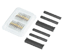
| Discrete-wire connector set (supplied) FP2 I/O unit and positioning unit supplied. | AFP2801 (2pieces) |
| Flat cable connector set(40 leads) For FP2 I/O unit and positioning unit. For simple connection using a flat cable. | AFP2802 (2pieces) |
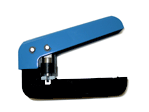
| Multi-wire connector pressure contact tool Necessary when wiring transistor output type connectors. | AXY52000FP |
Connector terminals
Connector terminals recommended for use with the FP7 and FP2SH
TOYOGIKEN CO., LTD.
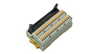
Connector terminal parts numbers
・PCXV-1H40 (straight, spring-lock terminals vertical type, poles: 40P)
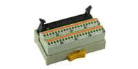
・PCX-1H40 (angled, spring-lock type, poles: 40P)
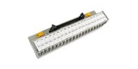
・PCN7-1H40 (crimping terminal type, poles: 40P)
Cable parts numbers
Cable: KB40N-1H1H-*MB (AWG28, unshielded)
*Cable length (m ft): 0.5 1.640 / 1 3.281 / 1.5 4.921 / 2 6.562 / 3 9.843 / 5 16.404
| To learn more about connector terminals, please contact TOYOGIKEN CO., LTD. URL:https://www.togi.co.jp/en/
|
------------------------------ Tab2 showing ------------------------------
Specifications
■Power supply / I/O Specifications
| Item | Description |
|---|---|
| Power supply | 100-120 V AC / 200-240 V AC / 100-240 V AC / 24 V DC (varies with different models) |
| Input | 12 to 24 V DC / 24 V DC ±common |
| Output | Relay 2 A to 5 A, Transistor 0.1 A to 0.5 A (varies with different models) |
■Performance Specifications
| Item | Description | ||
|---|---|---|---|
| Number of I/O points | Up to 768 points per one boad | ||
| Expansion | Standard | Up to 1 backplane, Units: 25 max., I/O points: 1,600 max., Remote I/O points: 8,192 max. | |
| H type | Up to 3 backplane, Units: 32 max., I/O points: 2,048 max., Remote I/O points: 8,192 max. | ||
| Operation speed | 0.03μs/step (Basic instuction) | ||
| Built-in memory | RAM (ROM/Small PC card is optional) | ||
| Memory capacity | 32 k steps approx. / 60 k steps approx. / 120 k steps approx. (varies with different models) | ||
| Operation memory | Internal relay | 14,192 points | |
| Timer/Counter (T/C) | 3,072 points in total | ||
| Data register | 10,240 words | ||
| File register | 32,765 words × 3 | ||
■Special Functions
| Item | Description | |
|---|---|---|
| Analog I/O | Available by adding analog input and analog output units. | |
| High speed counter | Available by adding high-speed counter unit. (Max. 200 kHz) | |
| Positioning | Available by adding positioning unit. (Max. 4 Mpps) * The positioning unit for RTEX can be used. | |
| Serial | RS-232C port | Standard equipped with CPU unit. Expandable by adding C.C.U., serial data unit and M.C.U. |
| RS-422 RS-485 | Expandable by adding M.C.U. | |
| Interrupt input | Available by adding high-speedcounter unit or pulse I/O unit. | |
■Special Network Functions
| Item | Description |
|---|---|
| Remote I/O | S-LINK, MEWNET-F |
| PLC Link | MEWNET-W2 (Wire) MEWNET-W0 MEWNET-VE FL-NET |
| Computer Link | Linkable by using tool port or COM. port on CPU unit. Also available by adding M.C.U. and C.C.U. |
| Modem connection | Available |
■Other Built-in Functions
| Item | Description |
|---|---|
| FP2SH | |
| Program block-edit during RUN | Available |
| Constant scan | Available |
| Clock / Calendar function | Built-in type |
------------------------------ Tab3 showing ------------------------------
Dimensions
Unit: mm in- FP2/FP2SH CPU Units
- FP2/FP2SH Backplanes
- FP2/FP2SH Power supply Units
- FP2/FP2SH I/O Units
- FP2/FP2SH Intelligent Units for Analog I/O
- FP2/FP2SH Positioning Control and Calculation Units
- FP2/FP2SH Link-related Intelligent Units and Software
FP2/FP2SH CPU Units
AFP22*1/AFP22*5

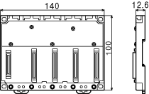
FP2/FP2SH Backplanes
AFP25005
FP2/FP2SH Power supply Units
AFP2631/AFP2632

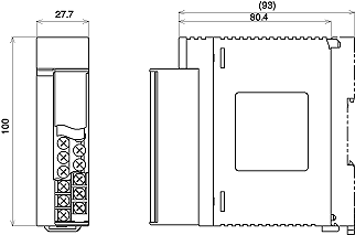
FP2/FP2SH I/O Units
AFP23**1/AFP23**3
FP2/FP2SH Intelligent Units for Analog I/O
AFP2410

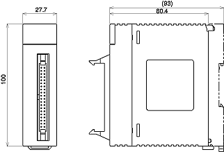
FP2/FP2SH Positioning Control and Calculation Units
AFP2432/AFP2434
FP2/FP2SH Link-related Intelligent Units and Software
AFP27901/AFP279601

------------------------------ Tab4 showing ------------------------------
Software
Programming Software
Setting Software
------------------------------ Tab5 showing ------------------------------
Compatibility with CPU unit
- Comparison of Specifications
- Compatibility of FP2SH and FP2, and Precautions
- Compatibility of FP2/FP2SH and FP10SH, and Precautions
- IC memory cards for the FP2SH
Comparison of Specifications
| Items | FP2SH CPU | FP10SH CPU | |||
|---|---|---|---|---|---|
| FP2-2L FP2-2 FP2-2P FP2-3P | AFP6221V3 | AFP6211V3 | |||
| Controllable I/O points | Basic construction | Using Backplanes: Max. 768 points (12 modules) Using Backplanes H type: Max. 512 points (8 modules) | Max. 512 points | ||
| Expanded construction | Using Backplanes: Max. 1,600 points (25 modules) Using Backplanes H type: Max. 2,048 points (32 modules) | Max. 2,048 points | |||
| Using remote I/O system | Max. 8,192 points | Max. 8,192 points | |||
| Program capacity | Internal memory | Approx. 60k steps (For FP2-3P, approx. 120k steps) | Approx. 30k steps | ||
| Using expansion memory | - | Approx. 60k steps/ 120k steps | |||
| Operation speed (typical value) | Basic instructions | From 0.03?s per instruction | From 0.04?s per instruction | From 0.10?s per instruction | |
| High-level instructions | From 0.06?s per instruction | From 0.08?s per instruction | From 0.20?s per instruction | ||
| Operation memory points | Relays | External input (X) | 8,192 points | 8,192 points | |
| External output (Y) | 8,192 points | 8,192 points | |||
| Internal relays (R) | 14,192 points | 14,192 points | |||
| Timer/counter (T/C) | Total 3,072 points | Total 3,072 points | |||
| Link relays (L) | 10,240 points | 10,240 points | |||
| Pulse relays (P) | 2,048 points | 2,048 points | |||
| Alarm relays (E) | 2,048 points | 2,048 points | |||
| Memory areas | Data registers (DT) | 10,240 words | 10,240 words | ||
| File registers (FL) | FP2-2L: 32,765 words FP2-2, FP2-2P, FP2-3P: 32,765 words × 3 banks | 32,765 words | |||
| Link data registers (LD) | 8,448 words | 8,448 words | |||
| Timer/counter set value area (SV) | 3,072 words | 3,072 words | |||
| Timer/counter elapsed value area (EV) | 3,072 words | 3,072 words | |||
| Index registers (I0 to ID) | 14 words× 16 banks | 14 words × 16 banks | |||
| Comment input function | Built - in (Internal) function | Optional function | |||
| Clock/calendar function | Built - in (Internal) function | Built - in (Internal) function | |||
| ROM operation function | FP2-2L, FP2-2: Optional function FP2-2P, FP2-3P: Built-in (Internal) function | Optional function | |||
Compatibility of FP2SH and FP2, and Precautions
Hardware Compatibility
Most of the units and related products used with the FP2SH can be used with the FP2, but the following differences should be noted.
Some optional memory units cannot be used.
The types of optional ROMs are different.
The backup battery types are different.
The calendar timer and comment memories have been installed in advance.
ROM operation functions in the FP2SH
- The only memory unit that can be used with the FP2SH CPU FP2-C2 or "FP2-C2L" is the "Part number FP2-M7 or Model number AFP2208".
- The FP2 memory units "Part numbers FP2-M1, FP2-M2, FP2-M3, and FP2-M6" cannot be used.
- The only ROM that can be used with the FP2SH CPU unit "FP2-C2" is the "Model number AFP5208 or AFP5209". The nonvolatile memory implemented memory unit "Model number AFP2208" can be also used.
- The FP2 ROM "Part number AFP2204" and "art number AFP2205" cannot be used.
- The backup battery for the FP2SH CPU is the "Part number AFP8801" battery with a connector.
- The "Part number AFC8801" battery for the FP2 CPU cannot be used.
- These have already been installed in the FP2SH CPU, and no optional units are needed.
- CPUs that support IC memory cards (FP2-C2P and FP2-C3P) have an internal FROM used as a program memory. The internal FROM cannot be replaced.
Software Compatibility
The FP2SH has a higher level of compatibility than the FP2, so there are no functions that cannot be used with the FP2SH.
Other factors, such as the number of device points, should be confirmed by checking the specifications comparison table on the previous page.
Compatibility of FP2/FP2SH and FP10SH, and Precautions
Hardware Compatibility
The unit, backplane, and other components are not compatible.
When using the FP2 backplane (AFP25**), the maximum number of expansion points is lower.
Different types of IC memory cards are used.
- The components for the FP2 are used with the FP2SH.
- With the FP10SH and FP2 backplane H type (AFP25**H), up to three expansion boards can be used, and a maximum of 2048 points controlled, but if using the FP2 backplane with the FP2/FP2SH, only one expansion board can be used, and a maximum of 1600 points controlled.
- The only type of IC card that can be used with the “Part number FP2-C2P and FP2-C3P” FP2SH CPU is the IC memory card (small PC card). The IC memory card for the FP10SH cannot be used.
Software Compatibility
With the FP2SH, in comparison with the FP10SH, there are no functions that cannot be used. For other detailed specifications, check the specifications comparison table on the previous page.
IC memory cards for the FP2SH
The existing model number becomes the one to be discontinued because of the termination of manufacturing IC memory cards by the parts manufacturer. When placing a new order, specify the new product number.
Termination of Production
| Type | Memory capacity | Model No. | Battery type |
|---|---|---|---|
| SRAM | 2MB | AIC52000 | Internal secondary battery (Rechargeable type) |
New product
| Type | Memory capacity | Model No. | Battery type |
|---|---|---|---|
| SRAM | 2MB | AFP2209 | Lithium Battery (Interchangeable type) |
Notes
For AFP2209
For AIC52000
- An interchangeable lithium battery is used. When you use for the first time, install the battery included.
- Memory backup of the SRAM type of IC memory card (AIC52000) Is handled by an internal secondary battery. When the battery is used for the first time, power must be supplied for at least 24 hours to charge it fully. When the battery is fully charged, data is backed up for more than three months with out the power being turned on. Normally, the card should be installed in the PLC and power supplied when using it. Failing to charge the battery periodically can reduce the backup period and the service life of the battery. The backup battery cannot be replaced.
------------------------------ Tab6 showing ------------------------------
Cautions For Use
Basic Configurations by number of slots

The building block scheme allows you to combine units as desired.
2-module units
A2 modules type power supply unit and 2 modules type CPU are available.
| Type | Part number |
|---|---|
| 100 to 240V AC type power supply unit | FP2-PSA3 |
| 24V DC type power supply unit | FP2-PSD2 |
| CPU with 64-point input | FP2-C1D |
| CPU with S-LINK | FP2-C1SL |
Mounting
The number of units that can be installed is determined by the number of modules of the backplane used, the power supply unit to be installed, and the CPU.
| 1 module type CPU | Standard type CPU |
| 2 modules type CPU | CPU with 64-point input, CPU with S-LINK |
| 1 module type power supply unit | 100V 2.5A, 200V 2.5A |
| 2 modules type power supply unit | 100 to 240V 5A, 24V DC 5A |
CPU backplane
FP2 backplane

* slots free: Number of slots where units can be installed
FP2 backplane H type
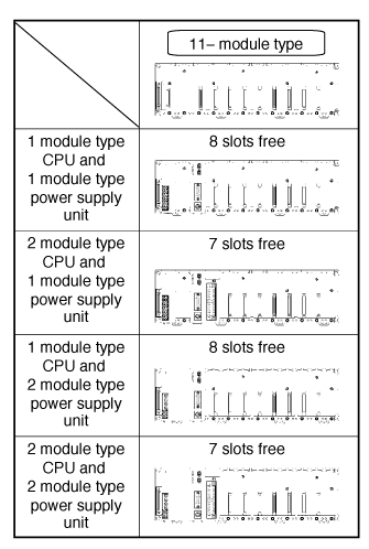
A maximum of eight I/O units (including the unit built in the CPU) can be controlled per backplane. Even if further I/O units are installed, they are not recognized.
Note)
When using the CPU unit with S-LINK, seven slots are free, however, the units actually usable are only six. (Refer to Chapter 3 I/O Allocation.)
Expansion of Backplane
FP2 backplane
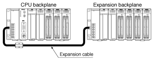
Only one backplane can be added-on for expansion.
Expansion is simply connecting a new backplane with a special expansion cable. Any backplane other than a 5-module type can be used for expansion.
Notes
- A 5-module type backplane cannot be expanded.
- A 5-module type backplane cannot be added on for expansion.
- Only one backplane can be added-on for expansion.
- A power supply unit is also necessary on an expansion backplane.
- Do not install a CPU on an expansion backplane.
- There is no need to make the number of modules on the expansion backplane equal to the number of modules on the CPU backplane.
FP2 backplane H type
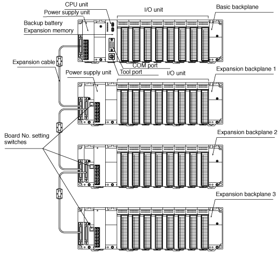
The basic FP2 backplane H type that the CPU unit can be installed and the expansion backplane H type that only the I/O units and the intelligent I/O units can be installed are available.
A maximum of eight I/O units (including the unit built in the CPU) can be controlled per backplane. Even if further I/O units are installed, they are not recognized.
Up to three expansion backplanes can be added on for expansion.
Use the board No. setting switches on the board to distinguish the expansion backplane.
A power supply unit is also necessary on an expansion backplane.
Mounting
The number of units that can be installed is determined by the number of modules of the backplane used and the power supply unit to be installed.
FP2 backplane

* slots free: Number of slots where units can be installed
FP2 backplane H type
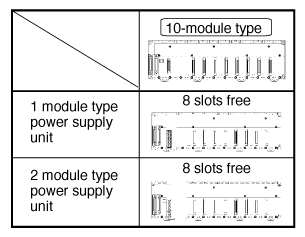
Note)
When using the CPU unit with S-LINK, seven slots are free, however, the units actually usable are only six. (Refer to Chapter 3 I/O Allocation.)
Expansion cable
| Order number | Length | Ferrite core |
|---|---|---|
| FP2-EC | 60 cm | 1 |
| FP2-EC2 | 2 m | 2 |
Note)
With the backplalne H type, the total cable length can be arranged within 3.2 m.

Restrictions on Unit Types
| Backplanes and units used | System configuration | ||||
|---|---|---|---|---|---|
| CPU backplane | Expansion backplane | Slave station system backplane | |||
| Install in order from the left to the right, the power supply unit, the CPU unit, the I/O and the intelligent units. | Install in order from the left to the right, the power supply unit, the I/O and the intelligent units. | Master backplane for slave station system | Expansion backplane for slave station system | ||
|
| Install in order from the left to the right, the power supply unit, the Remote I/O slave unit,the I/O and the intelligent units.*Replace the CPU on the CPU backplane with a remote I/O slave unit. | Install in order from the left to the right, the power supply unit, the I/O and the intelligent units.* Same as the installation of the expansion backplane. | ||
| Backplane | (5-module type) | Available | Not available | Available | Available |
| (7-, 9-, 12-, 14- module typs) | Available | Available | Available | Available | |
| Backplane H type | Basic (11-module type) | Available | Not available | Available | Available |
| Expansion (10-module type) | Not available | Available*4 | Not available | Available | |
| Power supply unit | Available | Available | Available | Available | |
| CPU unit | Available | Not available | Not available | Not available | |
| Remote I/O slave unit | Not available | Not available | Available | Not available | |
| Input unit | Available | Available | Available | Available | |
| Output unit | Available | Available | Available | Available | |
| I/O mixed unit | Available | Available | Available | Available | |
| Analog input unit | Available | Available | Not available | Not available | |
| Analog output unit | Available | Available | Not available | Not available | |
| High-speed counter unit | Availablenote 1) | Availablenote 1) note 5) | Availablenote 6) | Availablenote 6) | |
| Pulse I/O unit | Availablenote 1) | Availablenote 1) note 5) | Availablenote 6) | Availablenote 6) | |
| Positioning unit | Available | Available | Availablenote 7) | Availablenote 7) | |
| Positioning unit RTEX | Available | Available | Availablenote 7) | Availablenote 7) | |
| Positioning unit Interpolation type | Available | Available | Availablenote 7) | Availablenote 7) | |
| Serial data unit | Available | Available | Available | Available | |
| Computer communication unit | Availablenote 2) | Not available | Not available | Not available | |
| S-LINK unit | Available | Available | Not available | Not available | |
| Multi-wire link unit | MEWNET-F mode | Availablenote 3) | Availablenote 3) | Not available | Not available |
| MEWNET-W mode | Availablenote 2) | Not available | Not available | Not available | |
| MEWNET-W2 mode | Availablenote 2) | Not available | Not available | Not available | |
| ET-LAN2 unit | Availablenote 2) | Not available | Not available | Not available | |
| Multi Communication Unit | Availablenote 2) | Availablenote 2) | Not available | Not available | |
| MEWNET-VE2 Link Unit | Availablenote 2) | Not available | Not available | Not available | |
| FNS unit | Available | Available | Not available | Not available | |
| FMU unit | Available | Available | Not available | Not available | |
*1: When "Mode B: Unit with interrupt function" has been specified, the unit will be treated as interrupt unit, and 8 interrupts per unit will be available for use. However, when "Mode B" has been set for the unit, 2 units can be used with 1 CPU unit. When "Mode C: Intelligent unit that generate interrupts" has been specified, and 1 interrupt per unit will be available for use. However, when "Mode C" has been set for the unit, 8 units can be used with 1 CPU unit.
*2: Check the limitations on combining link units given below.
*3: In the MEWNET-F mode, up to four units counting the CPU and expansion sides.
*4: With the backplane H type, the total expansion cable length can be arranged within 3.2 m.
*5: The unit cannot be installed on the 32th slot (last slot) when using the H-type backplane.
*6: The interrupt function is not available for the backplane on the slave station system.
*7: With the backplane on the slave station system, the time taken from the startup until the completion of positioning should be longer than a scan time.
Limitations on Combining Link Units
| Unit type and mode | When CPU unit is FP2 | When CPU unit is FP2SH |
|---|---|---|
| Computer communication unit | Only 1 unit * | Can be installed within 3 units in combination with W link, CCU and MCU (PC link mode). |
| Multi-wire Link unit (MEWNET-W mode) | Can be installed within 5 units in combination with W link, CCU and MCU (PC link mode). | |
| Can be installed within 2 units in combination with MCU in PC (PLC) link mode. | ||
| Multi-wire Link unit (MEWNET-W2 mode)ET-LAN unit | Up to 3 units. Up to 2 units when a PLC link is included. | Up to 8 units. Up to 2 units when a PLC link is included. |
| Multi Communication Unit (PC(PLC) link mode) | Up to 3 units can be used. Up to 2 units out of 3, when including PC (PLC) link. | Up to 8 units can be used. Up to 2 units out of 8, when including PC (PLC) link. |
| Can be installed within 5 units in combination with W link, CCU and MCU. | ||
| Canbe installed within 2 units in combination withWlink unit in PC(PLC) link mode. | ||
| Multi Communication Unit (Computer link mode) | Up to 8 units can be used. | |
| MEWNET-VE2 Link Unit | Not available | Can be installed within 2 units in combination with Multi Communication Unit. |
*
Depending on the location of the connected boards and the commands used for communication, up to 3 units can be used. For more details, refer to the limitations on communication given on the next page and the Computer Communication Unit Manual.
Limitations on Current Consumption

| Product number | Part number | Rated current (5 V) |
|---|---|---|
| FP2-PSA1 | AFP2631 | 2.5 A |
| FP2-PSA2 | AFP2632 | 2.5 A |
| FP2-PSA3 | AFP2633 | 5 A |
| FP2-PSD2 | AFP2644 | 5 A |
Internal and External Power Supplies
Internal power supply (5 V DC)
5 V power supply used for driving the internal circuit of each unit is supplied from the power supply unit through the internal bus of the backplane.
External power supply (24 V DC)
- 24 V power supply used as the input power supply of input units and the output circuit driving power of output units is supplied from the external terminal.
For 24 V power supply, a commercial power supply unit is used.
Combining Units and Selecting a Backplane
The power consumed by each unit is shown in the next page. Give consideration to the combination of units so that the rated capacity of the 5 V and 24 V power supplies should not exceeded.
Examples of current consumption calculation
The table below shows the combinations of a 8-slot backplane and typical units.
| Item | Quantity | 5 V current consumption (mA) | 24 V current consumption (mA) |
|---|---|---|---|
| CPU unit (FP2-C1) | 1 | 410 | 0 |
| Master backplane (FP2-BP09) | 1 | 60 | 0 |
| Input unit (FP2-X16D2) | 3 | 60x3=180 | 8x16x3=384 |
| Output unit (FP2-Y16R) | 4 | 120x4=480 | 160x4=640 |
| Total current consumption | 1130 | 1024 |
Table of Current Consumption (5 V power supply)
| Item | Product number | Part number | 5 V power consumption (mA) | |||
|---|---|---|---|---|---|---|
| FP2SH CPU unit | FP2-C2 | AFP2231 | 750mA or less | |||
| FP2-C2P | AFP2235 | 750mA or less | ||||
| FP2-C3P | AFP2255 | 750mA or less | ||||
| Backplane | FP2-BP05 | AFP25005 | 5mA or less | |||
| FP2-BP07 | AFP25007 | 60mA or less | ||||
| FP2-BP09 | AFP25009 | 60mA or less | ||||
| FP2-BP12 | AFP25012 | 60mA or less | ||||
| FP2-BP14 | AFP25014 | 60mA or less | ||||
| Backplane H type | FP2-BP11MH | AFP25011MH | 60mA or less | |||
| FP2-BP10EH | AFP25010EH | 60mA or less | ||||
| Input unit | DC input | 16-point terminal block, 12 V to 24 V DC | FP2-X16D2 | AFP23023 | 60mA or less | |
| 32-point connector, 24 V DC | FP2-X32D2 | AFP23064 | 80mA or less | |||
| 64-point connector, 24 V DC | FP2-X64D2 | AFP23067 | 100mA or less | |||
| Output unit | Relay output | 6-point terminal block | FP2-Y6R | AFP23101 | 50mA or less | |
| 16-point terminal block | FP2-Y16R | AFP23103 | 120mA or less | |||
| Transistor output | 16-point terminal block, NPN | FP2-Y16T | AFP23403 | 100mA or less | ||
| 32-point connector, NPN | FP2-Y32T | AFP23404 | 130mA or less | |||
| 64-point connector, NPN | FP2-Y64T | AFP23407 | 210mA or less | |||
| 16-point terminal block, PNP | FP2-Y16P | AFP23503 | 80mA or less | |||
| 32-point connector, PNP | FP2-Y32P | AFP23504 | 130mA or less | |||
| 64-point connector, PNP | FP2-Y64P | AFP23507 | 210mA or less | |||
| I/O mixed unit | 32-point 24 V DC input/32-point connector, NPN output type | FP2-XY64D2T FP2-XY64D7T | AFP23467 AFP23477 | 160mA or less | ||
| 32-point 24 V DC input/32-point connector, PNP output type | FP2-XY64D2P FP2-XY64D7P | AFP23567 AFP23577 | 160mA or less | |||
| Intelligent unit | Analog input unit (Voltage/current type) | FP2-AD8VI | AFP2400L | 400mA or less | ||
| Analog input unit (Channel type) | FP2-AD8VI | AFP2401 | 300mA or less | |||
| RTD input unit | FP2-RTD | AFP2402 | 300mA or less | |||
| Analog output unit | FP2-DA4 | AFP2410 | 600mA or less | |||
| High-speed counter unit | NPN output | FP2-HSCT | AFP2441 | 450mA or less | ||
| PNP output | FP2-HSCP | AFP2451 | 450mA or less | |||
| Pulse I/O unit | NPN output | FP2-PXYT | AFP2442 | 500mA or less | ||
| PNP output | FP2-PXYP | AFP2452 | 500mA or less | |||
| Positioning unit | 2-axis type | FP2-PP2 | AFP2432 AFP2434 | 225mA or less | ||
| 4-axis type | FP2-PP4 | AFP2433 AFP2435 | 400mA or less | |||
| Positioning unit (Multifunction type) | 2-axis type | Transistor output type | FP2-PP21 | AFP2432 | 200mA or less | |
| Line driver output type | FP2-PP22 | AFP2434 | 200mA or less | |||
| 4-axis type | Transistor output type | FP2-PP41 | AFP2433 | 350mA or less | ||
| Line driver output type | FP2-PP42 | AFP2435 | 350mA or less | |||
| Positioning unit RTEX | 2-axis type | FP2-PN2AN | AFP243610 | 300mA or less | ||
| 4-axis type | FP2-PN4AN | AFP243620 | 300mA or less | |||
| 8-axis type | FP2-PN8AN | AFP243630 | 300mA or less | |||
| Positioning unit (Interpolation type) | 2-axis type | Transistor output type | FP2-PP2T | AFP243710 | 300mA or less | |
| Line driver output type | FP2-PP2L | AFP243711 | 300mA or less | |||
| 4-axis type | Transistor output type | FP2-PP4T | AFP243720 | 300mA or less | ||
| Line driver output type | FP2-PP4L | AFP243721 | 300mA or less | |||
| Serial data unit | FP2-SDU | AFP2460 | 60mA or less | |||
| Multi communication unit with Communication block (1-unit or 2-unit) * Soon, a sales schedule | FP2-MCU | AFP2465 | 480mA or less | |||
| Computer communication unit (C.C.U.) | FP2-CCU | AFP2462 | 60mA or less | |||
| S-LINK unit | 128 points, 1 ch | FP2-SL2 | AFP2780 | 130mA or less | ||
| Multi-wire link unit | FP2-MW | AFP2720 | 220mA or less | |||
| ET-LAN2 unit | FP2-ET1 | AFP27901 | 670mA or less | |||
Table of Current Consumption (24 V power supply)
| Item | Product number | Part number | 24 V power consumpion (mA) | ||
|---|---|---|---|---|---|
| Input unit | DC input | 16-point terminal block, 12 V to 24 V DC | FP2-X16D2 | AFP23023 | 8 mA or less/point |
| 32-point connector, 24 V DC | FP2-X32D2 | AFP23064 | 4.3 mA or less/point | ||
| 64-point connector, 24 V DC | FP2-X64D2 | AFP23067 | 4.3 mA or less/point | ||
| Output unit | Relay output | 6-point terminal block | FP2-Y6R | AFP23101 | 70mA or less |
| 16-point terminal block | FP2-Y16R | AFP23103 | 160mA or less | ||
| Transistor output | 16-point terminal block, NPN | FP2-Y16T | AFP23403 | 120mA or less | |
| 32-point connector, NPN | FP2-Y32T | AFP23404 | 140mA or less | ||
| 64-point connector, NPN | FP2-Y64T | AFP23407 | 250mA or less | ||
| 16-point terminal block, PNP | FP2-Y16P | AFP23503 | 70mA or less | ||
| 32-point connector, PNP | FP2-Y32P | AFP23504 | 150mA or less | ||
| 64-point connector, PNP | FP2-Y64P | AFP23507 | 270mA or less | ||
| I/O mixed unit | 32-point 24 V DC input / 32-point connector, NPN output type | FP2-XY64D2T FP2-XY64D7T | AFP23467 AFP23477 | Input :4.3 mA or less/point | |
| Output : 120 mA or less | |||||
| 32-point 24 V DC input / 32-point connector, PNP output type | FP2-XY64D2P FP2-XY64D7P | AFP23567 AFP23577 | Input : 4.3 mA or less/point | ||
| Output :130 mA or less | |||||
*1
The input unit displays the current flowing to the internal circuit. The other units display the current value required to drive the internal circuit.
This value dose not include the load current of the output unit.
*2
Refer to the manual of the each unit you are using to confirm the current consumed at 24 V by S-LINK related unit and the positioning unit.
