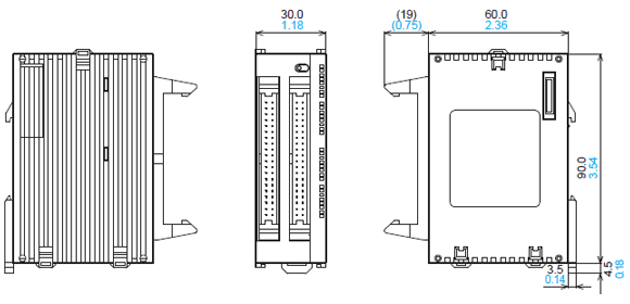
FPΣ (Discontinued Products)
Download
-
Discontinued Products
-
Specifications
-
Dimensions
-
Software
-
Cautions For Use
Ⅾiscontinued
Last time buy (JST)
September 30, 2021
------------------------------ Tab1 showing ------------------------------
Discontinued Products

[Note]
The following applicable products and options are available continuously.
FP0R Expansion units and FP0 Intelligent units can be used for FPΣ.
* Up to 3 Units can be connected.
Wiring Tools
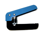
| Multi-wire connector pressure contact tool Necessary when wiring transistor output type connectors. | AXY52000FP |
Parts For Mounting
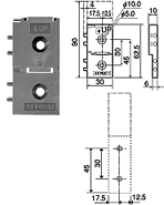
| FP0 Slim 30 type mounting plate Screw-stop attachment plate 30 mm 1.181 inch width type | AFP0811 (set of 10) |
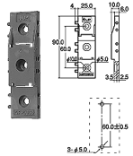
| Slim type mounting plate Screw-stop attachment plate. Slim model. | AFP0803 (set of 10) |
| Flat type mounting plate Screw-stop attachment plate. Flat model. | AFP0804 (set of 10) |
I/O Cables
| Transistor output type I/O cable(Length: 1 m 3.281 ft.) Wire-pressed terminal cable (10 leads) AWG22, 0.3 mm2 with connectors attached at one end, 1 set: 2 cables (blue and white). | AFP0521 |
| Transistor output type I/O cable(Length: 3 m 9.843 ft.) Wire-pressed terminal cable (10 leads) AWG22, 0.3 mm2 with connectors attached at one end, 1 set: 2 cables (blue and white). | AFP0523 |
* Two I/O cable sets (total 4 cables) are necessary.
Connector
| Flat cable connector set For FP2 I/O unit and positioning unit. For simple connection using a flat cable. | AFP2802 (2pieces) |
Additional Parts
| Terminal socket Attaches to relay output and terminal block type. Additional part | AFP0802 (2 sockets per pack) |
| Wire-press connector socket Attaches to transistor output type. Additional part | AFP0807 (2 sockets per pack) |
| FPΣ Power cable Attaches to control unit and relay output type expansion unit. Additional part Length: 1 m 3.281ft. | AFPG805 (1 cable per pack) |
| FPΣ Backup battery Backup for operation memory and clock/calender | AFPG804 |
| FPΣ High capacity battery holder Battery does not come with battery holder. | AFPG807 |
Connector terminals
Connector terminals recommended for use with the FPΣ
TOYOGIKEN CO., LTD.
・Connector poles: 20P (Control units etc.)
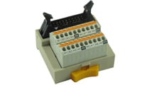
Connector terminal parts numbers
・PCX-1H20 (angled, spring-lock type, poles: 20P)
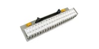
・PCN7-1H20 (crimping terminal type, poles: 20P)
Cable parts numbers
・Cable for connection to Panasonic Industry FP0R (custom-made)
SA14083-01-*M (Terminal Side 20P⇔PLC side 10Px2, unshielded)
*Cable length (m ft): 0.5 1.640 / 1 3.281 / 1.5 4.921 / 2 6.562 / 3 9.843
・Connector poles: 40P (Expansion units etc.)
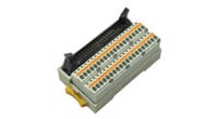
Connector terminal parts numbers
・PCXV-1H40 (straight, spring-lock terminals vertical type, poles: 40P)
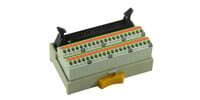
・PCX-1H40 (angled, spring-lock type, poles: 40P)
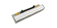
・PCN7-1H40 (crimping terminal type, poles: 40P)
Cable parts numbers
Cable: KB40N-1H1H-*MB (AWG28, unshielded)
*Cable length (m ft): 0.5 1.640 / 1 3.281 / 1.5 4.921 / 2 6.562 / 3 9.843 / 5 16.404
| To learn more about connector terminals, please contact TOYOGIKEN CO., LTD. URL:https://www.togi.co.jp/en/
|
------------------------------ Tab2 showing ------------------------------
Specifications
| Item | Description | ||||||
|---|---|---|---|---|---|---|---|
| AFPG2543H / AFPG2543HTM | AFPG2643H / AFPG2643HTM | AFPG2423H / AFPG2423HTM | AFPG2653H / AFPG2653HTM | ||||
| Number of controllable I/O points | Control unit | 32 points (DC input: 16, NPN output: 16) | 32 points (DC input: 16, NPN output: 16) | 24 points (DC input: 16, relay output: 8) | 28 points (DC input: 16, PNP output: 12) | ||
| With FP0R expansion units | Max. 128 points (up to 3 units) * When using transistor output type expansion units | Max. 128 points (up to 3 units) * When using transistor output type expansion units | Max. 120 points (up to 3 units) * When using transistor output type expansion units | Max. 124 points (up to 3 units) * When using transistor output type expansion units | |||
| With FPΣ expansion units | Not possible | Max. 288 points (up to 4 units) * When using transistor output type expansion units | Max. 280 points (up to 4 units) * When using transistor output type expansion units | Max. 284 points (up to 4 units) * When using NPN output type expansion units | |||
| With FP0R and FPΣ expansion units | Max. 128 points * When using transistor output type expansion units | Max. 384 points * When using transistor output type expansion units | Max. 376 points * When using transistor output type expansion units | Max. 380 points * When using NPN output type expansion units | |||
| Programming method / Control method | Relay symbol / Cyclic operation | ||||||
| Program memory / Program capacity | Built-in flash ROM (no backup battery required) / 32 k steps | ||||||
| Number of instructions | Basic instructions | 93 | |||||
| High-level instructions | 216 | 218 | 216 | 218 | |||
| Operation speed | Basic instruction: 0.32 μs~/step | ||||||
| Operation memory | Relay | Internal relay (R) | 4,096 points: R0 to R255F (Note 1) | ||||
| Timer / Counter (T/C) | 1,024 points (Note 1, 2) [for initial setting, timer: 1,008 points (T0 to T1007), counter: 16 points (C1008 to C1023)] Timer: Counts each unit up to 32,767 times (units: 1 ms, 10 ms, 100 ms, or 1 sec.). Counter: Counts 1 to 32,767. | ||||||
| Link relays (L) | 2,048 points | ||||||
| 32,765 words (DT0 to DT32764) (Note 1) | |||||||
| Memory area | Data register (DT) | 32,765 words (DT0 to DT32764) (Note 1) | |||||
| Link data register (LD) | 256 words | ||||||
| Index register (I) | 14 words (I0 to ID) | ||||||
| Differential points | Unlimited | ||||||
| Master control relay points (MCR) | 256 | ||||||
| Number of labels (JP and LOOP) | 256 | ||||||
| Number of step ladders | 1,000 stages | ||||||
| Number of subroutines | 100 subroutines | ||||||
| Pulse catch input | 8 points (X0 to X7) | ||||||
| Number of interrupt programs | 9 programs (8 external input points (X0 to X7), 1 periodical interrupt point 0.5 ms to 30 sec.) | ||||||
| Self-diagnosis function | E. g. watchdog timer, program syntax check | ||||||
| Clock / calendar function | Available year (last two digits), month, day, hour (24-hour display), minute, second and day of week; however, this function can only be used when a battery is installed. (Note 3) | ||||||
| Potentiometer (Volume) input | 2 points, resolution: 10 bits (K0 to K1000) | ||||||
| Battery life | 220 days or more (actual usage value: approx. 840 days (+25 ℃ +77 ℉). Suggested replacement interval: 1 year. (Value applies when no power is supplied at all.) | ||||||
| Comment storage | All kinds of comments, including I/O comments, remarks, and block comments, can be stored (without backup battery). | ||||||
| Link function | Computer link (1 : 1, 1 : N) (Note 4), General-purpose communication (1 : 1, 1 : N) (Note 4, 5), PLC link (Note 6) | ||||||
| Other functions | Program edition during RUN, constant scan, forced on/off, password, floating-point operation, and PID processing | ||||||
| Differential points | Linear/Circular interpolation for positioning | ||||||
Notes:
1) If no battery is used, only the fixed area is backed up (counters 16 points: C1008 to C1023, internal relays 128 points: R2480 to R255F, data registers 55 words: DT32710 to DT32764).
When the optional battery is used, data can be backed up. Areas to be held and not held can be specified using the system registers. (Exclusive instructions allow writing and reading data in flash ROM.)
2) The number of points can be increased by using an auxiliary timer.
3) Precision of calendar timer:
- At 0 ℃ +32 ℉, less than 119 seconds error per month.
- At +25 ℃ +77 ℉, less than 51 seconds error per month.
- At +55 ℃ +131 ℉, less than 148 seconds error per month.
4) An optional communication cassette (RS-232C type) is required in order to use 1 : 1 communication.
5) An optional communication cassette (RS-485 type) is required in order to use 1 : N communication.
6) An optional communication cassette (RS-485 type) is required.
When the communication cassette is attached and it communicates, re-send processing is recommended.
------------------------------ Tab3 showing ------------------------------
------------------------------ Tab4 showing ------------------------------
Software
Programming Software
Setting Software
------------------------------ Tab5 showing ------------------------------
Cautions For Use
Restrictions when combining unit and using programming tools
Expansion I/O units for the FPΣ
- 1.The left-side expansion type FPΣ control unit is necessary for use with the FPΣ expansion I/O unit.
The previously available control units (Product number: FPG-C32T/FPG-C32TTM. Part number: AFPG2543/AFPG2543TM) cannot be used for expansion. - 2.A maximum of four units can be used for expansion.
FPΣ and FP0 shared expansion I/O units and intelligence units
When combining expansion I/O units and intelligence units a maximum of up to three units can be added to the right side of control unit.
Programming tools
- 1.Either FPWIN GR Ver. 2 or FPWIN Pro Ver. 4 are necessary for use with the FPΣ control unit.
Users of FPWIN GR Ver. 1 will have to upgrade.
However, the upgrade only applies to Version 1.1 or higher. Those users with versions below Version 1.1 are asked to send us your user registration card. Upon receipt we will send you Version 1.1. - 2.Either FPWIN GR Ver. 2.1 or FPWIN Pro Ver. 4.1 are necessary for use the left-side expansion type FPΣ control unit. An upgrade service is available from software page
- 3.Handy-type programmers cannot be used with the FPΣ series PLC.
FP0 Power Supply Unit
Use is possible with the FPΣ Control Unit alone.
Unit's current consumption table
| Type of unit | Control unit current consumption | Expansion unit current consumption | Input circuit current consumption | Output circuit current consumption | |
|---|---|---|---|---|---|
| This is the current consumed from the control unit power supply connector. If expan-sion units or intelligent units are added, the current is increased by the value indicated below. | This is the current consumed from the expansion unit power supply connector. If a unit is not listed below, it means that it has no power supply connector | This is the current consumed by the input circuits of the various units. This value indicates the current that flows into the input circuit. | This is the current consumed by the output circuits of the various units. This value indicates the current used to drive the output circuits. This value does not include the load current value. | ||
| FPΣ control unit | FPG-C32 FPG-C28 | 90 mA or less | - | 77.2 mA or less | 70 mA or less |
| FPG-C24 | 160 mA or less | - | 77.2 mA or less | - | |
| FPΣ expansion unit | FPG-XY64D2T FPG-XY64D2P | 35 mA or less | - | 112 mA or less | 15 mA or less |
| FPΣ intelligent unit | FPG-PP11 FPG-PP12 | 50 mA or less | 20 mA or less | - | - |
| FPG-PP21 FPG-PP22 | 70 mA or less | 35 mA or less | - | - | |
| FPG-EM1 | 35 mA or less | - | - | - | |
| FPG-CCLS | 40 mA or less | 40 mA or less | - | - | |
| FPG-SL | 40 mA or less | - | - | - | |
| FP0 expansion unit | FP0-E8X | 10 mA or less | - | 34.4 mA or less | - |
| FP0-E8R | 15 mA or less | 50 mA or less | 17.2 mA or less | - | |
| FP0-E8YR | 10 mA or less | 100 mA or less | - | - | |
| FP0-E8YT/P | 15 mA or less | - | - | 24 mA or less | |
| FP0-E16X | 20 mA or less | - | 68.8 mA or less | - | |
| FP0-E16R | 20 mA or less | 100 mA or less | 34.4 mA or less | - | |
| FP0-E16T/P | 25 mA or less | - | 34.4 mA or less | 24 mA or less | |
| FP0-E16YT/P | 25 mA or less | - | - | 48 mA or less | |
| FP0-E32T/P | 40 mA or less | - | 68.8 mA or less | 48 mA or less | |
| FP0 intelligent unit | FP0-A21 | 20 mA or less | 100 mA or less | - | - |
| FP0-A80 | 20 mA or less | 60 mA or less | - | - | |
| FP0-A04V | 20 mA or less | 100 mA or less | - | - | |
| FP0-A04I | 20 mA or less | 130 mA or less | - | - | |
| FP0-TC4 FP0-TC8 | 25 mA or less | - | - | - | |
| FP0-IOL | 30 mA or less | 40 mA or less | - | - | |
| FP0-CCLS | 40 mA or less | 40 mA or less | - | - | |
| Communication cassette | FPG-COM1 FPG-COM2 | 20 mA or less | - | - | - |
| FPG-COM3 FPG-COM4 | 25 mA or less | - | - | -
| |
