Panasonic's concept of connecting 6 sets of Sensor heads to 1 Controller in series offers maximum flexibility to solve a wide range of safety applications. Just configure exactly the number of Sensor heads and controllers required to protect the area in question, e.g. small openings or irregularly shaped spaces impractical for Safety Light Curtains. A beam interruption indicator is incorporated in both the emitter and receiver to indicate operation and assist with beam alignment.
The high-functional Controller, ST4-C12EX, can immediately diagnose misaligned or abnormal Sensor heads. Its digital display shows errors immediately and supports both PNP and NPN polarities.
Characteristics
Series Connection Of 6 Sets Of Sensor Heads To 1 Controller
Compact Design
IP67 Degree Of Protection
Three Muting Function Patterns
High-Functional Type Controller
Safety Category 4
Compact Type 4 Safety Beam Sensor ST4
Part number list
Results 6
Models table for series Compact Type 4 Safety Beam Sensor ST4
Part No.
Datasheet
Applicable Standards
CE Marking Directive Compliance
Operating Range
Sensing Object
Effective Aperture Angle
Power Voltage
Current Consumption
Beam Interruption Indicator
Beam Emission Indicator
Stable Incident Beam Indicator
PFHD
MTTFD
Environmental Resistance: Degree of Protection
Ambient Temperature
Ambient Humidity
Ambient Illuminance
Environmental Resistance: Dielectric Strength Voltage
Insulation Resistance
Vibration Resistance
Shock Resistance
Emitting Element
Material
Cable
Cable Extension
Weight (Total Of Emitter And Receiver)
Applicable Sensor Head
Applicable Sensor Head: No. Of Series Connections
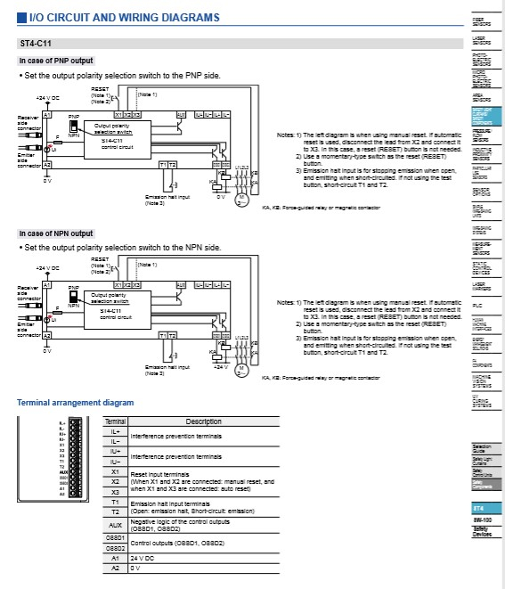
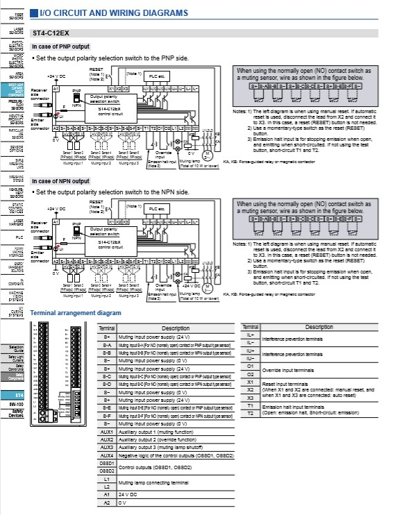
Control Outputs (OSSD 1, OSSD 2)
Control Outputs (OSSD 1, OSSD 2): Operation Mode
Control Outputs (OSSD1, OSSD2): Protection Circuit
IEC 61496-1/2 (JIS B 9704-1/2 / UL 61496-1/2) (Type 4), ISO 13849-1 (Category 4, PLe), JIS B 9705-1 (Category 4), IEC 61508-1 to 7 (SIL3), IEC 62061 (SIL3), JIS C 0508-1 to 7 (SIL3), UL 1998, OSHA 1910.212, OSHA 1910.217 (C), ANSI B11.1 to B11.19, ANSI/RIA R15.06, ANSI/ISA S84.01 (SIL3) (Note) Complies with those standards only when the controller is used in combination with the sensor head ST4-x.
Refer to the following table(Note: (Probability of dangerous failure per hour) depends on number of single beam sensor ST4-A□ connected to controller.)
More than 100 years (Note:Mean time to dangerous failure (in years))
Enclosure: IP40 (IEC) Terminal: IP20 (IEC)
−10 to +55 ℃ +14 to +131 ℉ (No dew condensation or icing allowed), Storage: −25 to +70 ℃ −13 to +158 ℉
30 to 85 % RH, Storage: 30 to 95 % RH
1,000 V AC for one min. between all supply terminals connected together and enclosure
20 MOhm or more with 500 V DC mega between all supply terminals connected together and enclosure
10 to 55 Hz frequency, 0.75 mm 0.030 in double amplitude or maximum acceleration 90 m/s2 in X, Y and Z directions for two hours each<
300 m/s2 acceleration in X, Y and Z directions three times each
Enclosure: ABS
ST4-Ax
Interference prevention possible when up to a maximum of 6 sets are connected(When the maximum of 3 controllers are connected together, interference prevention is possible for up to 18 sets)
PNP open-collector transistor / NPN open-collector transistor Dual output x 1 system (Set using output polarity selection switch) [PNP output] Maximum source current: 200 mA Applied voltage: same as the supply voltage (between control output and +V) Residual voltage: 2.5 V or less (at 200 mA source current) Leakage current: 200 micro A or less (including power OFF condition) Maximum load capacity: 1 micro F (from no-load to max. source current) Load wiring resistance: 3 Ohm or less (between control output and load) [NPN output] Maximum sink current: 200 mA Applied voltage: same as the supply voltage (between control output and 0 V) Residual voltage: 2.0 V or less (at 200 mA sink current) Leakage current: 200 micro A or less (including power OFF condition) Maximum load capacity: 1 micro F (from no-load to max. sink current) Load wiring resistance: 3 Ohm or less (between control output and load) (Note) If the total current of the control outputs (OSSD1, OSSD2), auxiliary outputs, and muting lamp output exceeds 400 mA, the wiring resistance between the controller and the power supply should be 1 Ohm or less. In addition, if the total current is 400 mA or less, the wiring resistance between the controller and the power supply should be 2 Ohm or less.
ON when all beams of the connected ST4-Axs are received OFF when one or more beams of the connected ST4-Axs are interrupted(except during muting / override) OFF during lockout
Incorporated
OFF response: 25 ms or less ON response: 90 ms or less (auto reset) / 140 ms or less (manual reset)
PNP open-collector transistor / NPN open-collector transistor (Set using output polarity selection switch) ST4-C11: one output ST4-C12EX: four outputs [PNP output] Maximum source current: 100 mA Applied voltage: same as the supply voltage (between auxiliary output and +V) Residual voltage: 2.5 V or less (at 100 mA source current) [NPN output] Maximum sink current: 100 mA Applied voltage: same as the supply voltage (between auxiliary output and 0 V) Residual voltage: 2.0 V or less (at 100 mA sink current) (Note) If the total current of the control outputs (OSSD1, OSSD2), auxiliary outputs, and muting lamp output exceeds 400 mA, the wiring resistance between the controller and the power supply should be 1 Ohm or less. In addition, if the total current is 400 mA or less, the wiring resistance between the controller and the power supply should be 2 Ohm or less.
ON when muting function is invalid OFF when muting function is valid
ON when override function is invalid OFF when override function is valid
ON when muting lamp is in normal condition OFF when muting lamp is in abnormal condition
Negative logic of the control outputs (OSSD1, OSSD2)
Incorporated
Available muting lamp: 24 V DC, 1 to 10 W (Note) If the total current of the control outputs (OSSD1, OSSD2), auxiliary outputs, and muting lamp output exceeds 400 mA, the wiring resistance between the controller and the power supply should be 1 Ohm or less. In addition, if the total current is 400 mA or less, the wiring resistance between the controller and the power supply should be 2 Ohm or less.
Incorporated
Detachable spring-cage terminal
Terminal block connector: 0.2 to 1.5 mm2 Power supply connector (A1, A2): 0.2 to 2.5 mm2
Net weight: 240 g approx Gross weight: 450 g approx
IEC 61496-1/2 (JIS B 9704-1/2 / UL 61496-1/2) (Type 4), ISO 13849-1 (Category 4, PLe), JIS B 9705-1 (Category 4), IEC 61508-1 to 7 (SIL3), IEC 62061 (SIL3), JIS C 0508-1 to 7 (SIL3), UL 1998, OSHA 1910.212, OSHA 1910.217 (C), ANSI B11.1 to B11.19, ANSI/RIA R15.06, ANSI/ISA S84.01 (SIL3) (Note) Complies with those standards only when the sensor head is used in combination with the controller ST4-C11 / ST4-C12EX.
0.1 to 15 m 0.328 to 49.213 ft (Note:The operating range is the possible setting distance between the emitter and the receiver. It can detect sensing object of less than 0.1 m 0.328 ft away.)
φ9 mm φ0.354 in or more opaque object
plus or minus 2.5degrees or less for operating range exceeding 3 m 9.843 ft (required by IEC 61496-2 / UL 61496-2)
Supplied from controller
Emitter: 11 mA or less Receiver: 9 mA or less
Red LED (lights up when the beam is interrupted or lock out, lights off during reception) (Note) Shows light interruption information between the emitter and the receiver with the same address. It does not show OSSD output.
Green LED (lights up during beam emission, lights off during emission halt)
Green LED (lights up under stable light received condition, lights off under unstable light received condition)
IP67 (IEC)
−10 to +55 ℃ +14 to +131 ℉ (No dew condensation or icing allowed), Storage: −25 to +70 ℃ −13 to +158 ℉
30 to 85 % RH, Storage: 30 to 95 % RH
Incandescent lamp: 3,500 Lx or less at the light-receiving face
1,000 V AC for one min. between all supply terminals connected together and enclosure
20 MOhm or more with 500V DC megger between all supply terminals connected together and enclosure
10 to 55 Hz frequency, 0.75 mm 0.030 in double amplitude or maximum acceleration 90 m/s2 in X, Y and Z directions for two hours each<
300 m/s2 acceleration in X, Y and Z directions three times each
Infrared LED (Peak emission wavelength: 870 nm 0.034 mil)
IEC 61496-1/2 (JIS B 9704-1/2 / UL 61496-1/2) (Type 4), ISO 13849-1 (Category 4, PLe), JIS B 9705-1 (Category 4), IEC 61508-1 to 7 (SIL3), IEC 62061 (SIL3), JIS C 0508-1 to 7 (SIL3), UL 1998, OSHA 1910.212, OSHA 1910.217 (C), ANSI B11.1 to B11.19, ANSI/RIA R15.06, ANSI/ISA S84.01 (SIL3) (Note) Complies with those standards only when the controller is used in combination with the sensor head ST4-x.
Refer to the following table(Note: (Probability of dangerous failure per hour) depends on number of single beam sensor ST4-A□ connected to controller.)
More than 100 years (Note:Mean time to dangerous failure (in years))
Enclosure: IP40 (IEC) Terminal: IP20 (IEC)
−10 to +55 ℃ +14 to +131 ℉ (No dew condensation or icing allowed), Storage: −25 to +70 ℃ −13 to +158 ℉
30 to 85 % RH, Storage: 30 to 95 % RH
1,000 V AC for one min. between all supply terminals connected together and enclosure
20 MOhm or more with 500 V DC mega between all supply terminals connected together and enclosure
10 to 55 Hz frequency, 0.75 mm 0.030 in double amplitude or maximum acceleration 90 m/s2 in X, Y and Z directions for two hours each<
300 m/s2 acceleration in X, Y and Z directions three times each
Enclosure: ABS
ST4-Ax
Interference prevention possible when up to a maximum of 6 sets are connected(When the maximum of 3 controllers are connected together, interference prevention is possible for up to 18 sets)
PNP open-collector transistor / NPN open-collector transistor Dual output x 1 system (Set using output polarity selection switch) [PNP output] Maximum source current: 200 mA Applied voltage: same as the supply voltage (between control output and +V) Residual voltage: 2.5 V or less (at 200 mA source current) Leakage current: 200 micro A or less (including power OFF condition) Maximum load capacity: 1 micro F (from no-load to max. source current) Load wiring resistance: 3 Ohm or less (between control output and load) [NPN output] Maximum sink current: 200 mA Applied voltage: same as the supply voltage (between control output and 0 V) Residual voltage: 2.0 V or less (at 200 mA sink current) Leakage current: 200 micro A or less (including power OFF condition) Maximum load capacity: 1 micro F (from no-load to max. sink current) Load wiring resistance: 3 Ohm or less (between control output and load) (Note) If the total current of the control outputs (OSSD1, OSSD2), auxiliary outputs, and muting lamp output exceeds 400 mA, the wiring resistance between the controller and the power supply should be 1 Ohm or less. In addition, if the total current is 400 mA or less, the wiring resistance between the controller and the power supply should be 2 Ohm or less.
ON when all beams of the connected ST4-Axs are received OFF when one or more beams of the connected ST4-Axs are interrupted OFF during lockout
Incorporated
OFF response: 25 ms or less ON response: 90 ms or less (auto reset) / 140 ms or less (manual reset)
PNP open-collector transistor / NPN open-collector transistor (Set using output polarity selection switch) ST4-C11: one output ST4-C12EX: four outputs [PNP output] Maximum source current: 100 mA Applied voltage: same as the supply voltage (between auxiliary output and +V) Residual voltage: 2.5 V or less (at 100 mA source current) [NPN output] Maximum sink current: 100 mA Applied voltage: same as the supply voltage (between auxiliary output and 0 V) Residual voltage: 2.0 V or less (at 100 mA sink current) (Note) If the total current of the control outputs (OSSD1, OSSD2), auxiliary outputs, and muting lamp output exceeds 400 mA, the wiring resistance between the controller and the power supply should be 1 Ohm or less. In addition, if the total current is 400 mA or less, the wiring resistance between the controller and the power supply should be 2 Ohm or less.
OFF when all beams of the connected ST4-Axs are received ON when one or more beams of the connected ST4-Axs are interrupted
Incorporated
- (Note) If the total current of the control outputs (OSSD1, OSSD2), auxiliary outputs, and muting lamp output exceeds 400 mA, the wiring resistance between the controller and the power supply should be 1 Ohm or less. In addition, if the total current is 400 mA or less, the wiring resistance between the controller and the power supply should be 2 Ohm or less.
Incorporated
Detachable spring-cage terminal
Terminal block connector: 0.2 to 1.5 mm2
Net weight: 180 g approx Gross weight: 390 g approx
IEC 61496-1/2 (JIS B 9704-1/2 / UL 61496-1/2) (Type 4), ISO 13849-1 (Category 4, PLe), JIS B 9705-1 (Category 4), IEC 61508-1 to 7 (SIL3), IEC 62061 (SIL3), JIS C 0508-1 to 7 (SIL3), UL 1998, OSHA 1910.212, OSHA 1910.217 (C), ANSI B11.1 to B11.19, ANSI/RIA R15.06, ANSI/ISA S84.01 (SIL3) (Note) Complies with those standards only when the sensor head is used in combination with the controller ST4-C11 / ST4-C12EX.
0.1 to 15 m 0.328 to 49.213 ft (Note:The operating range is the possible setting distance between the emitter and the receiver. It can detect sensing object of less than 0.1 m 0.328 ft away.)
φ9 mm φ0.354 in or more opaque object
plus or minus 2.5degrees or less for operating range exceeding 3 m 9.843 ft (required by IEC 61496-2 / UL 61496-2)
Supplied from controller
Emitter: 11 mA or less Receiver: 9 mA or less
Red LED (lights up when the beam is interrupted or lock out, lights off during reception) (Note) Shows light interruption information between the emitter and the receiver with the same address. It does not show OSSD output.
Green LED (lights up during beam emission, lights off during emission halt)
Green LED (lights up under stable light received condition, lights off under unstable light received condition)
IP67 (IEC)
−10 to +55 ℃ +14 to +131 ℉ (No dew condensation or icing allowed), Storage: −25 to +70 ℃ −13 to +158 ℉
30 to 85 % RH, Storage: 30 to 95 % RH
Incandescent lamp: 3,500 Lx or less at the light-receiving face
1,000 V AC for one min. between all supply terminals connected together and enclosure
20 MOhm or more with 500V DC megger between all supply terminals connected together and enclosure
10 to 55 Hz frequency, 0.75 mm 0.030 in double amplitude or maximum acceleration 90 m/s2 in X, Y and Z directions for two hours each<
300 m/s2 acceleration in X, Y and Z directions three times each
Infrared LED (Peak emission wavelength: 870 nm 0.034 mil)
IEC 61496-1/2 (JIS B 9704-1/2 / UL 61496-1/2) (Type 4), ISO 13849-1 (Category 4, PLe), JIS B 9705-1 (Category 4), IEC 61508-1 to 7 (SIL3), IEC 62061 (SIL3), JIS C 0508-1 to 7 (SIL3), UL 1998, OSHA 1910.212, OSHA 1910.217 (C), ANSI B11.1 to B11.19, ANSI/RIA R15.06, ANSI/ISA S84.01 (SIL3) (Note) Complies with those standards only when the controller is used in combination with the sensor head ST4-x.
Refer to the following table(Note: (Probability of dangerous failure per hour) depends on number of single beam sensor ST4-A□ connected to controller.)
More than 100 years (Note:Mean time to dangerous failure (in years))
Enclosure: IP40 (IEC) Terminal: IP20 (IEC)
−10 to +55 ℃ +14 to +131 ℉ (No dew condensation or icing allowed), Storage: −25 to +70 ℃ −13 to +158 ℉
30 to 85 % RH, Storage: 30 to 95 % RH
1,000 V AC for one min. between all supply terminals connected together and enclosure
20 MOhm or more with 500 V DC mega between all supply terminals connected together and enclosure
10 to 55 Hz frequency, 0.75 mm 0.030 in double amplitude or maximum acceleration 90 m/s2 in X, Y and Z directions for two hours each<
300 m/s2 acceleration in X, Y and Z directions three times each
Enclosure: ABS
ST4-Ax
Interference prevention possible when up to a maximum of 6 sets are connected(When the maximum of 3 controllers are connected together, interference prevention is possible for up to 18 sets)
PNP open-collector transistor / NPN open-collector transistor Dual output x 1 system (Set using output polarity selection switch) [PNP output] Maximum source current: 200 mA Applied voltage: same as the supply voltage (between control output and +V) Residual voltage: 2.5 V or less (at 200 mA source current) Leakage current: 200 micro A or less (including power OFF condition) Maximum load capacity: 1 micro F (from no-load to max. source current) Load wiring resistance: 3 Ohm or less (between control output and load) [NPN output] Maximum sink current: 200 mA Applied voltage: same as the supply voltage (between control output and 0 V) Residual voltage: 2.0 V or less (at 200 mA sink current) Leakage current: 200 micro A or less (including power OFF condition) Maximum load capacity: 1 micro F (from no-load to max. sink current) Load wiring resistance: 3 Ohm or less (between control output and load) (Note) If the total current of the control outputs (OSSD1, OSSD2), auxiliary outputs, and muting lamp output exceeds 400 mA, the wiring resistance between the controller and the power supply should be 1 Ohm or less. In addition, if the total current is 400 mA or less, the wiring resistance between the controller and the power supply should be 2 Ohm or less.
ON when all beams of the connected ST4-Axs are received OFF when one or more beams of the connected ST4-Axs are interrupted(except during muting / override) OFF during lockout
Incorporated
OFF response: 25 ms or less ON response: 90 ms or less (auto reset) / 140 ms or less (manual reset)
PNP open-collector transistor / NPN open-collector transistor (Set using output polarity selection switch) ST4-C11: one output ST4-C12EX: four outputs [PNP output] Maximum source current: 100 mA Applied voltage: same as the supply voltage (between auxiliary output and +V) Residual voltage: 2.5 V or less (at 100 mA source current) [NPN output] Maximum sink current: 100 mA Applied voltage: same as the supply voltage (between auxiliary output and 0 V) Residual voltage: 2.0 V or less (at 100 mA sink current) (Note) If the total current of the control outputs (OSSD1, OSSD2), auxiliary outputs, and muting lamp output exceeds 400 mA, the wiring resistance between the controller and the power supply should be 1 Ohm or less. In addition, if the total current is 400 mA or less, the wiring resistance between the controller and the power supply should be 2 Ohm or less.
ON when muting function is invalid OFF when muting function is valid
ON when override function is invalid OFF when override function is valid
ON when muting lamp is in normal condition OFF when muting lamp is in abnormal condition
Negative logic of the control outputs (OSSD1, OSSD2)
Incorporated
Available muting lamp: 24 V DC, 1 to 10 W (Note) If the total current of the control outputs (OSSD1, OSSD2), auxiliary outputs, and muting lamp output exceeds 400 mA, the wiring resistance between the controller and the power supply should be 1 Ohm or less. In addition, if the total current is 400 mA or less, the wiring resistance between the controller and the power supply should be 2 Ohm or less.
Incorporated
Detachable spring-cage terminal
Terminal block connector: 0.2 to 1.5 mm2 Power supply connector (A1, A2): 0.2 to 2.5 mm2
Net weight: 240 g approx Gross weight: 450 g approx
IEC 61496-1/2 (JIS B 9704-1/2 / UL 61496-1/2) (Type 4), ISO 13849-1 (Category 4, PLe), JIS B 9705-1 (Category 4), IEC 61508-1 to 7 (SIL3), IEC 62061 (SIL3), JIS C 0508-1 to 7 (SIL3), UL 1998, OSHA 1910.212, OSHA 1910.217 (C), ANSI B11.1 to B11.19, ANSI/RIA R15.06, ANSI/ISA S84.01 (SIL3) (Note) Complies with those standards only when the sensor head is used in combination with the controller ST4-C11 / ST4-C12EX.
0.1 to 15 m 0.328 to 49.213 ft (Note:The operating range is the possible setting distance between the emitter and the receiver. It can detect sensing object of less than 0.1 m 0.328 ft away.)
φ9 mm φ0.354 in or more opaque object
plus or minus 2.5degrees or less for operating range exceeding 3 m 9.843 ft (required by IEC 61496-2 / UL 61496-2)
Supplied from controller
Emitter: 11 mA or less Receiver: 9 mA or less
Red LED (lights up when the beam is interrupted or lock out, lights off during reception) (Note) Shows light interruption information between the emitter and the receiver with the same address. It does not show OSSD output.
Green LED (lights up during beam emission, lights off during emission halt)
Green LED (lights up under stable light received condition, lights off under unstable light received condition)
IP67 (IEC)
−10 to +55 ℃ +14 to +131 ℉ (No dew condensation or icing allowed), Storage: −25 to +70 ℃ −13 to +158 ℉
30 to 85 % RH, Storage: 30 to 95 % RH
Incandescent lamp: 3,500 Lx or less at the light-receiving face
1,000 V AC for one min. between all supply terminals connected together and enclosure
20 MOhm or more with 500V DC megger between all supply terminals connected together and enclosure
10 to 55 Hz frequency, 0.75 mm 0.030 in double amplitude or maximum acceleration 90 m/s2 in X, Y and Z directions for two hours each<
300 m/s2 acceleration in X, Y and Z directions three times each
Infrared LED (Peak emission wavelength: 870 nm 0.034 mil)
IEC 61496-1/2 (JIS B 9704-1/2 / UL 61496-1/2) (Type 4), ISO 13849-1 (Category 4, PLe), JIS B 9705-1 (Category 4), IEC 61508-1 to 7 (SIL3), IEC 62061 (SIL3), JIS C 0508-1 to 7 (SIL3), UL 1998, OSHA 1910.212, OSHA 1910.217 (C), ANSI B11.1 to B11.19, ANSI/RIA R15.06, ANSI/ISA S84.01 (SIL3) (Note) Complies with those standards only when the sensor head is used in combination with the controller ST4-C11 / ST4-C12EX.
0.1 to 15 m 0.328 to 49.213 ft (Note:The operating range is the possible setting distance between the emitter and the receiver. It can detect sensing object of less than 0.1 m 0.328 ft away.)
φ9 mm φ0.354 in or more opaque object
plus or minus 2.5degrees or less for operating range exceeding 3 m 9.843 ft (required by IEC 61496-2 / UL 61496-2)
Supplied from controller
Emitter: 11 mA or less Receiver: 9 mA or less
Red LED (lights up when the beam is interrupted or lock out, lights off during reception) (Note) Shows light interruption information between the emitter and the receiver with the same address. It does not show OSSD output.
Green LED (lights up during beam emission, lights off during emission halt)
Green LED (lights up under stable light received condition, lights off under unstable light received condition)
IP67 (IEC)
−10 to +55 ℃ +14 to +131 ℉ (No dew condensation or icing allowed), Storage: −25 to +70 ℃ −13 to +158 ℉
30 to 85 % RH, Storage: 30 to 95 % RH
Incandescent lamp: 3,500 Lx or less at the light-receiving face
1,000 V AC for one min. between all supply terminals connected together and enclosure
20 MOhm or more with 500V DC megger between all supply terminals connected together and enclosure
10 to 55 Hz frequency, 0.75 mm 0.030 in double amplitude or maximum acceleration 90 m/s2 in X, Y and Z directions for two hours each<
300 m/s2 acceleration in X, Y and Z directions three times each
Infrared LED (Peak emission wavelength: 870 nm 0.034 mil)
IEC 61496-1/2 (JIS B 9704-1/2 / UL 61496-1/2) (Type 4), ISO 13849-1 (Category 4, PLe), JIS B 9705-1 (Category 4), IEC 61508-1 to 7 (SIL3), IEC 62061 (SIL3), JIS C 0508-1 to 7 (SIL3), UL 1998, OSHA 1910.212, OSHA 1910.217 (C), ANSI B11.1 to B11.19, ANSI/RIA R15.06, ANSI/ISA S84.01 (SIL3) (Note) Complies with those standards only when the controller is used in combination with the sensor head ST4-x.
Refer to the following table(Note: (Probability of dangerous failure per hour) depends on number of single beam sensor ST4-A□ connected to controller.)
More than 100 years (Note:Mean time to dangerous failure (in years))
Enclosure: IP40 (IEC) Terminal: IP20 (IEC)
−10 to +55 ℃ +14 to +131 ℉ (No dew condensation or icing allowed), Storage: −25 to +70 ℃ −13 to +158 ℉
30 to 85 % RH, Storage: 30 to 95 % RH
1,000 V AC for one min. between all supply terminals connected together and enclosure
20 MOhm or more with 500 V DC mega between all supply terminals connected together and enclosure
10 to 55 Hz frequency, 0.75 mm 0.030 in double amplitude or maximum acceleration 90 m/s2 in X, Y and Z directions for two hours each<
300 m/s2 acceleration in X, Y and Z directions three times each
Enclosure: ABS
ST4-Ax
Interference prevention possible when up to a maximum of 6 sets are connected(When the maximum of 3 controllers are connected together, interference prevention is possible for up to 18 sets)
PNP open-collector transistor / NPN open-collector transistor Dual output x 1 system (Set using output polarity selection switch) [PNP output] Maximum source current: 200 mA Applied voltage: same as the supply voltage (between control output and +V) Residual voltage: 2.5 V or less (at 200 mA source current) Leakage current: 200 micro A or less (including power OFF condition) Maximum load capacity: 1 micro F (from no-load to max. source current) Load wiring resistance: 3 Ohm or less (between control output and load) [NPN output] Maximum sink current: 200 mA Applied voltage: same as the supply voltage (between control output and 0 V) Residual voltage: 2.0 V or less (at 200 mA sink current) Leakage current: 200 micro A or less (including power OFF condition) Maximum load capacity: 1 micro F (from no-load to max. sink current) Load wiring resistance: 3 Ohm or less (between control output and load) (Note) If the total current of the control outputs (OSSD1, OSSD2), auxiliary outputs, and muting lamp output exceeds 400 mA, the wiring resistance between the controller and the power supply should be 1 Ohm or less. In addition, if the total current is 400 mA or less, the wiring resistance between the controller and the power supply should be 2 Ohm or less.
ON when all beams of the connected ST4-Axs are received OFF when one or more beams of the connected ST4-Axs are interrupted OFF during lockout
Incorporated
OFF response: 25 ms or less ON response: 90 ms or less (auto reset) / 140 ms or less (manual reset)
PNP open-collector transistor / NPN open-collector transistor (Set using output polarity selection switch) ST4-C11: one output ST4-C12EX: four outputs [PNP output] Maximum source current: 100 mA Applied voltage: same as the supply voltage (between auxiliary output and +V) Residual voltage: 2.5 V or less (at 100 mA source current) [NPN output] Maximum sink current: 100 mA Applied voltage: same as the supply voltage (between auxiliary output and 0 V) Residual voltage: 2.0 V or less (at 100 mA sink current) (Note) If the total current of the control outputs (OSSD1, OSSD2), auxiliary outputs, and muting lamp output exceeds 400 mA, the wiring resistance between the controller and the power supply should be 1 Ohm or less. In addition, if the total current is 400 mA or less, the wiring resistance between the controller and the power supply should be 2 Ohm or less.
OFF when all beams of the connected ST4-Axs are received ON when one or more beams of the connected ST4-Axs are interrupted
Incorporated
- (Note) If the total current of the control outputs (OSSD1, OSSD2), auxiliary outputs, and muting lamp output exceeds 400 mA, the wiring resistance between the controller and the power supply should be 1 Ohm or less. In addition, if the total current is 400 mA or less, the wiring resistance between the controller and the power supply should be 2 Ohm or less.
Incorporated
Detachable spring-cage terminal
Terminal block connector: 0.2 to 1.5 mm2
Net weight: 180 g approx Gross weight: 390 g approx
IEC 61496-1/2 (JIS B 9704-1/2 / UL 61496-1/2) (Type 4), ISO 13849-1 (Category 4, PLe), JIS B 9705-1 (Category 4), IEC 61508-1 to 7 (SIL3), IEC 62061 (SIL3), JIS C 0508-1 to 7 (SIL3), UL 1998, OSHA 1910.212, OSHA 1910.217 (C), ANSI B11.1 to B11.19, ANSI/RIA R15.06, ANSI/ISA S84.01 (SIL3) (Note) Complies with those standards only when the sensor head is used in combination with the controller ST4-C11 / ST4-C12EX.
0.1 to 15 m 0.328 to 49.213 ft (Note:The operating range is the possible setting distance between the emitter and the receiver. It can detect sensing object of less than 0.1 m 0.328 ft away.)
φ9 mm φ0.354 in or more opaque object
plus or minus 2.5degrees or less for operating range exceeding 3 m 9.843 ft (required by IEC 61496-2 / UL 61496-2)
Supplied from controller
Emitter: 11 mA or less Receiver: 9 mA or less
Red LED (lights up when the beam is interrupted or lock out, lights off during reception) (Note) Shows light interruption information between the emitter and the receiver with the same address. It does not show OSSD output.
Green LED (lights up during beam emission, lights off during emission halt)
Green LED (lights up under stable light received condition, lights off under unstable light received condition)
IP67 (IEC)
−10 to +55 ℃ +14 to +131 ℉ (No dew condensation or icing allowed), Storage: −25 to +70 ℃ −13 to +158 ℉
30 to 85 % RH, Storage: 30 to 95 % RH
Incandescent lamp: 3,500 Lx or less at the light-receiving face
1,000 V AC for one min. between all supply terminals connected together and enclosure
20 MOhm or more with 500V DC megger between all supply terminals connected together and enclosure
10 to 55 Hz frequency, 0.75 mm 0.030 in double amplitude or maximum acceleration 90 m/s2 in X, Y and Z directions for two hours each<
300 m/s2 acceleration in X, Y and Z directions three times each
Infrared LED (Peak emission wavelength: 870 nm 0.034 mil)
IEC 61496-1/2 (JIS B 9704-1/2 / UL 61496-1/2) (Type 4), ISO 13849-1 (Category 4, PLe), JIS B 9705-1 (Category 4), IEC 61508-1 to 7 (SIL3), IEC 62061 (SIL3), JIS C 0508-1 to 7 (SIL3), UL 1998, OSHA 1910.212, OSHA 1910.217 (C), ANSI B11.1 to B11.19, ANSI/RIA R15.06, ANSI/ISA S84.01 (SIL3) (Note) Complies with those standards only when the sensor head is used in combination with the controller ST4-C11 / ST4-C12EX.
0.1 to 15 m 0.328 to 49.213 ft (Note:The operating range is the possible setting distance between the emitter and the receiver. It can detect sensing object of less than 0.1 m 0.328 ft away.)
φ9 mm φ0.354 in or more opaque object
plus or minus 2.5degrees or less for operating range exceeding 3 m 9.843 ft (required by IEC 61496-2 / UL 61496-2)
Supplied from controller
Emitter: 11 mA or less Receiver: 9 mA or less
Red LED (lights up when the beam is interrupted or lock out, lights off during reception) (Note) Shows light interruption information between the emitter and the receiver with the same address. It does not show OSSD output.
Green LED (lights up during beam emission, lights off during emission halt)
Green LED (lights up under stable light received condition, lights off under unstable light received condition)
IP67 (IEC)
−10 to +55 ℃ +14 to +131 ℉ (No dew condensation or icing allowed), Storage: −25 to +70 ℃ −13 to +158 ℉
30 to 85 % RH, Storage: 30 to 95 % RH
Incandescent lamp: 3,500 Lx or less at the light-receiving face
1,000 V AC for one min. between all supply terminals connected together and enclosure
20 MOhm or more with 500V DC megger between all supply terminals connected together and enclosure
10 to 55 Hz frequency, 0.75 mm 0.030 in double amplitude or maximum acceleration 90 m/s2 in X, Y and Z directions for two hours each<
300 m/s2 acceleration in X, Y and Z directions three times each
Infrared LED (Peak emission wavelength: 870 nm 0.034 mil)