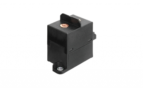
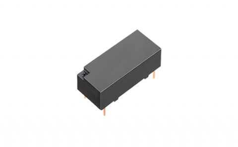
Specifications
| Item | Performance characteristics |
|---|---|
| Terminal Type | Screw terminal |
| Coil Terminal Structure | Connector |
| Rated Coil Voltage | 12V DC |
| Contact Capacity | 120 A |
| Protective Construction | Capsule contact |
| Operating Function | Single side stable |
| Operate (Set) Voltage (at20°C) (Initial) | Max. 9 V DC |
| Release (Reset) voltage (at20℃) (Initial) | Min. 1 V DC |
| Rated Operating Current [±10%] (at 20°C) | 0.353 A |
| Coil Resistance (At 20oC) | 34Ω |
| Rated Operating Power (at 20°C) | 4.2 W |
| Max. applied voltage | 16V DC |
| Contact Arrangement | 1 Form A |
| Contact Material | Copper alloy |
| Nominal Switching Capacity (Resistive Load) | 120A 450V DC (Carry, 38mm2 wire) |
| Max. Carring Current | 120A Continuity 225A 3 min. 400A 30 sec. (38mm2 wire) |
| Min. Switching Load (Resistive) | 1A 12V DC (at 20°C) |
| Contact Voltage Drop (Initial) | Max. 0.03 V (by voltage drop 6 V DC 20 A) |
| Insulation Resistance (Min. MΩ)(Initial) | Min. 100 MΩ (At 500 V DC, Measured portion is the same as the case of dielectric strength.) |
| Dielectric Strength (Between Open Contacts) (Initial) | 2,500 Vrms for 1min. (detection current: 10mA.) |
| Dielectric Strength (Between Contacts and Coil) (Initial) | 2,500 Vrms for 1min. (detection current: 10mA.) |
| Operate (Set) Time<br>(At Rated Coil Voltage) (At 20oC) (Initial) | Max. 50 ms (without bounce) |
| Release (Reset) Time<br>(at Rated Coil Voltage) (at 20°C) (Initial) | Max. 30 ms (with no coil protective elements) |
| Shock Resistance: Functional | For ON: Min. 196 m/s2 (half-sine shock pulse: 11 ms, detection time: 10 µs) For OFF: Min. 98 m/s2 (half-sine shock pulse: 11 ms, detection time: 10 µs) |
| Shock Resistance: Destructive | Min. 490 m/s2 (half-sine shock pulse: 6 ms) |
| Vibration Resistance: Functional | 10 to 200 Hz, 43 m/s2 (detection time: 10 µs) |
| Vibration Resistance: Destructive | 10 to 200 Hz, 43 m/s2 (Time of vibration for each direction; X, Y, Z direction: 4 hours) |
| Expected Life: Mechanical Life | Min. 2 x 10⁵ |
| Expected Life: Electrical Life (Resistive) | 30A 450V DC, Min. 1,000 operations |
| Expected Life: Switch-Off Life | [Forward direction]: 1,200 A 300 V DC, Min. 1 cycle 120 A 450 V DC, Min. 50 operations [Reverse direction]: -120 A 200 V DC, Min. 50 operations |
| Expected Life: Inrush Current (Capacitor) | 120 A 20 V DC, Min. 70,000 operations |
| Conditions | Ambient temperature: –40 to +80°C Humidity: 5 to 85% R.H. (Avoid icing when using at temperatures lower than 0°C.) |
| Weight (Typ.) | Approx. 400 g |
| Inner Carton (Pieces) | 1 |
| Outer Carton (Pieces) | 20 |
| Usable Voltage Range | 10 V DC to 16 V DC |
Stock check
AEV14012
Resources
Filter by:
Showing 1 to 7 of 7 results
Results7
What's New
Stay up to date
Latest Videos
Playlist

Smart Grid Products: LF-G Series Power Relays

Smart Grid Products: HE-V Series Power Relays

New Product Spotlight: DW Series Relays

New Product Spotlight: PA-N Series General Power Relays
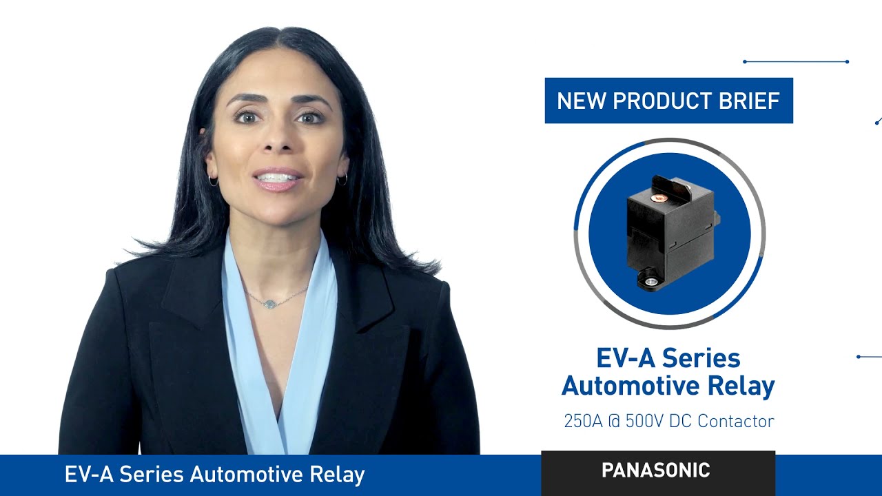
New Product Brief: EV-A Series Automotive Relay

New Product Brief: TB Series Automotive Relays
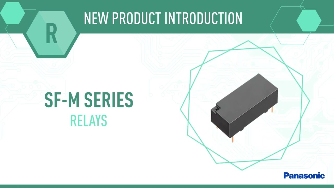
NPI: SF-M Series Relays

SF-M Series Safety Relays

New Product Introduction: HE-R Series General Power Relays
