| | EMC Directive, RoHS Directive, UL/c-UL Certification | Gauge pressure | −100.0 to +100.0 kPa | -101.0 to +101.0kPa | 500kPa | Non-corrosive gas | 12 to 24 V DC ±10 % Ripple P-P 10 % or less | Normal operation: 720 mW or less (Current consumption 30 mA or less at 24 V supply voltage)
ECO mode: 480 mW or less at STD (Current consumption 20 mA or less at 24 V supply voltage)
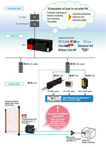
360 mW or less at FULL (Current consumption 15 mA or less at 24 V supply voltage) | IO-Link Specification V1.1
(Note:)When the sensor is used as an ordinary sensor, the communication output (C/Q) provides the same output operation as the control output (DO). | COM3 (230.4 kbps)
(Note:)When the sensor is used as an ordinary sensor, the communication output (C/Q) provides the same output operation as the control output (DO). | 4 byte
(Note:)When the sensor is used as an ordinary sensor, the communication output (C/Q) provides the same output operation as the control output (DO). | 1.0ms
(Note:)When the sensor is used as an ordinary sensor, the communication output (C/Q) provides the same output operation as the control output (DO). | PNP open-collector transistor
•Maximum source current: 50 mA
• Applied voltage: 30 V DC or less (between output and +V)
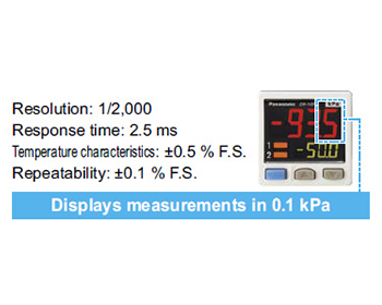
• Residual voltage: 2 V or less (at 50 mA source current) | N.O./N.C. (selectable by key operation) | EASY mode / Hysteresis mode / Window comparator mode | Minimum 1 digit (variable) | ±0.1 % F.S. (within ±2 digits) | 2.5 ms, 5 ms, 10 ms, 25 ms, 50 ms, 100 ms, 250 ms, 500 ms, 1,000 ms, 5,000 ms, selectable by key operation | Incorporated | 4 digits + 4 digits 3-color LCD display (Display refresh rate: 250 ms, 500 ms, 1,000 ms, selectable by key operation) | -101.0 to +101.0 kPa | Orange LED(Output operation indicator 1: Flashes during IO-Link communication, Lights up when the control output is ON during non-IO-Link communication (synchronized with the output operation indicator 2)
Output operation indicator 2: Lights up when the control output is ON) | IP40(IEC) | −10 to +50℃ +14 to +122 ℉(No dew condensation or icing allowed), Storage: −10 to +60℃ +14 to +140 ℉ | 35 to 85 % RH, Storage: 35 to 85 % RH | 1,000 V AC for one min. between all supply terminals connected together and enclosure | 50 MΩ or more with 500 V DC megger between all supply terminals connected together and enclosure | 10 to 500 Hz frequency, 3 mm 0.118 in double amplitude or maximum acceleration 196 m/s2, in X, Y and Z directions for two hours each(when panel or flat attachment is mounted: 10 to 150 Hz frequency, 0.75 mm 0.030 in double amplitude or maximum acceleration 49 m/s2, in X, Y and Z directions for two hours each) | 100 m/s2 acceleration (10 G approx.) in X, Y and Z directions three times each | Within ±0.5 % F.S.
(at +20℃ +68℉) | M5 female thread | Enclosure: PBT (glass fiber reinforced), LCD display: Acrylic, Pressure port: Stainless steel (SUS303) , Mounting threaded part: Brass (nickel plated), Switch part: Silicone rubber | Connector | Total length up to 20 m 65.617 ft (Condition of CE compliance less than 20 m 65.617 ft) is possible with 0.3 mm2, or more, cable. | Net weight: 30 g approx., Gross weight: 125 g approx. | CN-14A-C2 (Connector attached cable 2 m 6.562 ft): 1 pc. | (Note:)measurement conditions have not been specified precisely, the conditions used were an ambient temperature of +20℃ +68℉. |
| | EMC Directive, RoHS Directive, UL/c-UL Certification | Gauge pressure | −100.0 to +100.0 kPa | -101.0 to +101.0kPa | 500kPa | Non-corrosive gas | 12 to 24 V DC ±10 % Ripple P-P 10 % or less | Normal operation: 720 mW or less (Current consumption 30 mA or less at 24 V supply voltage)
ECO mode: 480 mW or less at STD (Current consumption 20 mA or less at 24 V supply voltage)
360 mW or less at FULL (Current consumption 15 mA or less at 24 V supply voltage) | IO-Link Specification V1.1
(Note:)When the sensor is used as an ordinary sensor, the communication output (C/Q) provides the same output operation as the control output (DO). | COM3 (230.4 kbps)
(Note:)When the sensor is used as an ordinary sensor, the communication output (C/Q) provides the same output operation as the control output (DO). | 4 byte
(Note:)When the sensor is used as an ordinary sensor, the communication output (C/Q) provides the same output operation as the control output (DO). | 1.0ms
(Note:)When the sensor is used as an ordinary sensor, the communication output (C/Q) provides the same output operation as the control output (DO). | PNP open-collector transistor
•Maximum source current: 50 mA
• Applied voltage: 30 V DC or less (between output and +V)
• Residual voltage: 2 V or less (at 50 mA source current) | N.O./N.C. (selectable by key operation) | EASY mode / Hysteresis mode / Window comparator mode | Minimum 1 digit (variable) | ±0.1 % F.S. (within ±2 digits) | 2.5 ms, 5 ms, 10 ms, 25 ms, 50 ms, 100 ms, 250 ms, 500 ms, 1,000 ms, 5,000 ms, selectable by key operation | Incorporated | 4 digits + 4 digits 3-color LCD display (Display refresh rate: 250 ms, 500 ms, 1,000 ms, selectable by key operation) | -101.0 to +101.0 kPa | Orange LED(Output operation indicator 1: Flashes during IO-Link communication, Lights up when the control output is ON during non-IO-Link communication (synchronized with the output operation indicator 2)
Output operation indicator 2: Lights up when the control output is ON) | IP40(IEC) | −10 to +50℃ +14 to +122 ℉(No dew condensation or icing allowed), Storage: −10 to +60℃ +14 to +140 ℉ | 35 to 85 % RH, Storage: 35 to 85 % RH | 1,000 V AC for one min. between all supply terminals connected together and enclosure | 50 MΩ or more with 500 V DC megger between all supply terminals connected together and enclosure | 10 to 500 Hz frequency, 3 mm 0.118 in double amplitude or maximum acceleration 196 m/s2, in X, Y and Z directions for two hours each(when panel or flat attachment is mounted: 10 to 150 Hz frequency, 0.75 mm 0.030 in double amplitude or maximum acceleration 49 m/s2, in X, Y and Z directions for two hours each) | 100 m/s2 acceleration (10 G approx.) in X, Y and Z directions three times each | Within ±0.5 % F.S.
(at +20℃ +68℉) | M5 female thread | Enclosure: PBT (glass fiber reinforced), LCD display: Acrylic, Pressure port: Stainless steel (SUS303) , Mounting threaded part: Brass (nickel plated), Switch part: Silicone rubber | Connector | Total length up to 20 m 65.617 ft (Condition of CE compliance less than 20 m 65.617 ft) is possible with 0.3 mm2, or more, cable. | Net weight: 30 g approx., Gross weight: 95 g approx. | Dedicated M12 connector cable, 0.3 m 0.984 ft long: 1 pc. | (Note:)measurement conditions have not been specified precisely, the conditions used were an ambient temperature of +20℃ +68℉. |
| | EMC Directive, RoHS Directive, UL/c-UL Certification | Gauge pressure | -0.100 to +1.000 Mpa | -0.101 to +1.010MPa | 1.5MPa | Non-corrosive gas | 12 to 24 V DC ±10 % Ripple P-P 10 % or less | Normal operation: 720 mW or less (Current consumption 30 mA or less at 24 V supply voltage)
ECO mode: 480 mW or less at STD (Current consumption 20 mA or less at 24 V supply voltage)
360 mW or less at FULL (Current consumption 15 mA or less at 24 V supply voltage) | IO-Link Specification V1.1
(Note:)When the sensor is used as an ordinary sensor, the communication output (C/Q) provides the same output operation as the control output (DO). | COM3 (230.4 kbps)
(Note:)When the sensor is used as an ordinary sensor, the communication output (C/Q) provides the same output operation as the control output (DO). | 4 byte
(Note:)When the sensor is used as an ordinary sensor, the communication output (C/Q) provides the same output operation as the control output (DO). | 1.0ms
(Note:)When the sensor is used as an ordinary sensor, the communication output (C/Q) provides the same output operation as the control output (DO). | PNP open-collector transistor
•Maximum source current: 50 mA
• Applied voltage: 30 V DC or less (between output and +V)
• Residual voltage: 2 V or less (at 50 mA source current) | N.O./N.C. (selectable by key operation) | EASY mode / Hysteresis mode / Window comparator mode | Minimum 1 digit (variable) | ±0.2 % F.S. (within ±2 digits) | 2.5 ms, 5 ms, 10 ms, 25 ms, 50 ms, 100 ms, 250 ms, 500 ms, 1,000 ms, 5,000 ms, selectable by key operation | Incorporated | 4 digits + 4 digits 3-color LCD display (Display refresh rate: 250 ms, 500 ms, 1,000 ms, selectable by key operation) | -0.101 to +1.010MPa | Orange LED(Output operation indicator 1: Flashes during IO-Link communication, Lights up when the control output is ON during non-IO-Link communication (synchronized with the output operation indicator 2)
Output operation indicator 2: Lights up when the control output is ON) | IP40(IEC) | −10 to +50℃ +14 to +122 ℉(No dew condensation or icing allowed), Storage: −10 to +60℃ +14 to +140 ℉ | 35 to 85 % RH, Storage: 35 to 85 % RH | 1,000 V AC for one min. between all supply terminals connected together and enclosure | 50 MΩ or more with 500 V DC megger between all supply terminals connected together and enclosure | 10 to 500 Hz frequency, 3 mm 0.118 in double amplitude or maximum acceleration 196 m/s2, in X, Y and Z directions for two hours each(when panel or flat attachment is mounted: 10 to 150 Hz frequency, 0.75 mm 0.030 in double amplitude or maximum acceleration 49 m/s2, in X, Y and Z directions for two hours each) | 100 m/s2 acceleration (10 G approx.) in X, Y and Z directions three times each | Within ±1 % F.S.
(at +20℃ +68℉) | M5 female thread | Enclosure: PBT (glass fiber reinforced), LCD display: Acrylic, Pressure port: Stainless steel (SUS303) , Mounting threaded part: Brass (nickel plated), Switch part: Silicone rubber | Connector | Total length up to 20 m 65.617 ft (Condition of CE compliance less than 20 m 65.617 ft) is possible with 0.3 mm2, or more, cable. | Net weight: 30 g approx., Gross weight: 125 g approx. | CN-14A-C2 (Connector attached cable 2 m 6.562 ft): 1 pc. | (Note:)measurement conditions have not been specified precisely, the conditions used were an ambient temperature of +20℃ +68℉. |


