| | 96 | 1,910 mm
75.197 in
(Note): When using as a safety device for a press machine in China or when using SF4D-□-01 as a safety device for a press machine or paper shearing machine in Japan, the length from the center of the first beam channel to the center of the last beam channel become to be protective height. | 1,900 mm
74.803 in
(Note): When using as a safety device for a press machine in China or when using SF4D-□-01 as a safety device for a press machine or paper shearing machine in Japan, the length from the center of the first beam channel to the center of the last beam channel become to be protective height. | | Emitter : 120 mA or less
Receiver : 160 mA or less | 4.30×10⁻⁹ | 272 years or more | 4,800g approx. | IEC 61496-
1/2 (Type 4), ISO 13849-
1 (Category 4, PLe), IEC 61508-1 to 7 (SIL3) | JIS B 9704-1/2 (Type 4), JIS B 9705-1 (Category 4), JIS C 0508-1 to 7 (SIL3) | EN ISO 13849-1 (Category 4, PLe), EN 55011, EN 61000-6-2, EN IEC 63000 | ANSI/UL 61496-1/2 (Type 4),CAN/CSA C22.2 No.14, CAN/CSA E61496-1/2 | | GB/T 4584 | Machinery Directive, EMC Directive, RoHS Directive | Short mode : 0.2 to 9 m 0.656 to 29.528 ft
Long mode : 0.8 to 15 m 2.625 to 49.213 ft
(selectable by DIP switch)
(Note): The operating range is the possible setting distance between the emitter and the receiver. | ø25 mm ø0.984 in opaque object
(Note): When the floating blanking function is used, the size of the minimum sensing object varies. For the detail, refer to the section on Safety distance. | ±2.5° or less at a sensing range of 3 m 9.843 ft or longer (based on IEC 61496-2) | 24 V DC+20-30 % Ripple P-P 10 % or less (excluding voltage drop due to cable)
(Note): In consideration of the voltage drop caused by the cable, use Control output (OSSD 1, OSSD 2) source / sink current and cable length as a guideline. | PNP open-collector transistor / NPN open collector transistor (selectable)
・Maximum source current : 350 mA
・Applied voltage : Same as supply voltage
(between control output and +V)
・Residual voltage : 2 V or less (source current 350 mA)
(excluding voltage drop due to cable)
・Leakage current : 0.2 mA or less (including power OFF state)
・Maximum load capacity : 2.2 μF
・Load wiring resistance : 3 Ω or less
・Maximum sink current : 350 mA
・Applied voltage : Same as supply voltage
(between control output and 0 V)
・Residual voltage : 2 V or less (sink current 350 mA)
(excluding voltage drop due to cable)
・Leakage current : 0.2 mA or less (including power OFF state)
・Maximum load capacity : 2.2 μF
・Load wiring resistance : 3 Ω or less | ON when all beams are received, OFF when one or more beams are blocked
(Also OFF when internal sensor error or synchronization signal error occurs)
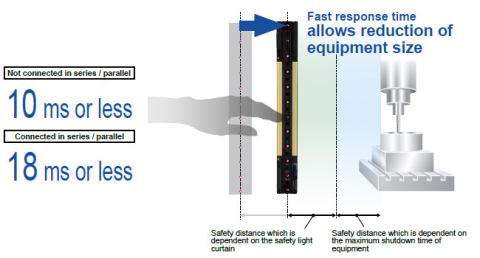
(Note): Note that the setting cannot be changed when SF4D-□-01 is used. | Incorporated | OFF response : 10 ms or less (Not connected in series / parallel), 18 ms or less (Connected in series / parallel)(Note 1)
ON response : 50 ms or less (Note 2)(Note 3)
(Note 1): For response times by number of beams, refer to the Control output (OSSD 1, OSSD 2) OFF response times.
(Note 2): Because the control output (OSSD 1, OSSD 2) must be OFF for at least 80 ms, the ON response will be delayed more than 50 ms when the light blocked time is less than 30 ms.
(Note 3): When optical synchronization is selected, if the beam axes of both the top end and bottom end are blocked, the ON response speed decreases by as much as 1 sec. | PNP open-collector transistor / NPN open collector transistor (selectable)
・Maximum source current : 60 mA
・Applied voltage : Same as supply voltage
(between auxiliary output and +V)
・Residual voltage : 2 V or less (source current 60 mA)
(excluding voltage drop due to cable)
・Leakage current : 0.2 mA or less (including power OFF state)
・Maximum sink current : 60 mA
・Applied voltage : Same as supply voltage
(between auxiliary output and 0 V)
・Residual voltage : 2 V or less (sink current 60 mA)
(excluding voltage drop due to cable)
・Leakage current : 0.2 mA or less (including power OFF state) | Control output ON : OFF, Control output OFF : ON
(Note): Note that the setting cannot be changed when SF4D-□-01 is used. | Incorporated | OFF response : 60 ms or less, ON response : 60 ms or less | Line synchronization / optical synchronization (selectable by DIP switch) |
・Line synchronization : 2 units or less (auto)
・Optical synchronization : 2 units or less (selectable by DIP switch)
・Series connection : 5 units or less (total number of beam channels 256 or less)
・Parallel connection : 3 units or less (total number of beam channels 192 or less)(Note)
・Series / parallel connection mixed : 5 units or less (total number of beam channels 144 or less)(Note)
(Note): Note that the setting cannot be changed when SF4D-□-01 is used.
| Incorporated | Incorporated [Manual reset / auto reset (selectable by wiring)] (8-core cable or 12-core cable) | Incorporated | Incorporated (8-core cable or 12-core cable) | Incorporated (only the receiver lights up when optical synchronization is used) | Incorporated (12-core cable) | Incorporated (12-core cable) | Incorporated | Optional functions cannot be used when SF4D-□-01 is used. | 3 | 2,000 m 6,561.68 ft or less
(Note): Do not use or store in an environment pressurized to atmospheric pressure or higher at an altitude of 0 m. | IP67, IP65 (IEC), NEMA Type 13 (NEMA 250) | -10 to +55 ℃ +14 to +131 ℉ (No dew condensation or icing allowed), Storage : -25 to +60 ℃ -13 to +140 ℉ | 30 to 85 % RH, Storage : 30 to 95 % RH | Incandescent light : 5,000 ℓx or less at the light-receiving surface | 1,000 V AC for one minute, between all supply terminals connected together and enclosure | 20 MΩ, or more, with 500 V DC megger, between all supply terminals connected together and enclosure | 10 to 55 Hz, 0.75 mm 0.030 in double amplitude in X, Y, and Z directions for two hours each
Malfunction resistance 10 to 55 Hz, 0.75 mm 0.030 in double amplitude in X, Y, and Z directions twenty times each | 300 m/s2 acceleration (30 G approx.) in X, Y, and Z directions three times each
Malfunction resistance 100 m/s2 acceleration (10 G approx.) in X, Y, and Z directions 1,000 times each | 99% | 1 | Type B (IEC 61508-2) | 20 years | Within response time (OFF response) | Control output (OSSD 1 / 2) OFF state | Infrared LED (peak emission wavelength : 850 nm 0.0335 mil) | Enclosure : Aluminum, Detection surface : Polycarbonate resin and stainless steel (SUS304), Upper cap / lower cap : Nylon | By connector | Total length of emitter / receiver can be extended up to 70 m 229.659 ft each using optional mating cable (including the length
of series mating cables)
(Note): In consideration of the voltage drop caused by the cable, use Control output (OSSD 1, OSSD 2) source / sink current and cable length as a guideline. | SF4B-TR25 (test rod) : 1 pc. | Where measurement conditions have not been specified precisely, the conditions used were an ambient temperature of +20 ℃ +68 ℉.
PFHD : Probability of Dangerous Failure per Hour, MTTFD : Mean Time to Dangerous Failure (in years). | | GB/T 4584 | CE Marking (Machinery Directive, EMC Directive, RoHS Directive) , TÜV SÜD certification,TÜV SÜD NRTL certification (U.S.A., Canada), OSHA 1910.212, OSHA 1910.217(C), ANSI B11.1 to B11.19, ANSI/RIA 15.06 |
| | 80 | 1,590 mm
62.598 in
(Note): When using as a safety device for a press machine in China or when using SF4D-□-01 as a safety device for a press machine or paper shearing machine in Japan, the length from the center of the first beam channel to the center of the last beam channel become to be protective height. | 1,580 mm
62.205 in
(Note): When using as a safety device for a press machine in China or when using SF4D-□-01 as a safety device for a press machine or paper shearing machine in Japan, the length from the center of the first beam channel to the center of the last beam channel become to be protective height. | | Emitter : 120 mA or less
Receiver : 150 mA or less | 3.69×10⁻⁹ | 318 years or more | 4,000g approx. | IEC 61496-
1/2 (Type 4), ISO 13849-
1 (Category 4, PLe), IEC 61508-1 to 7 (SIL3) | JIS B 9704-1/2 (Type 4), JIS B 9705-1 (Category 4), JIS C 0508-1 to 7 (SIL3) | EN ISO 13849-1 (Category 4, PLe), EN 55011, EN 61000-6-2, EN IEC 63000 | ANSI/UL 61496-1/2 (Type 4),CAN/CSA C22.2 No.14, CAN/CSA E61496-1/2 | | GB/T 4584 | Machinery Directive, EMC Directive, RoHS Directive | Short mode : 0.2 to 9 m 0.656 to 29.528 ft
Long mode : 0.8 to 15 m 2.625 to 49.213 ft
(selectable by DIP switch)
(Note): The operating range is the possible setting distance between the emitter and the receiver. | ø25 mm ø0.984 in opaque object
(Note): When the floating blanking function is used, the size of the minimum sensing object varies. For the detail, refer to the section on Safety distance. | ±2.5° or less at a sensing range of 3 m 9.843 ft or longer (based on IEC 61496-2) | 24 V DC+20-30 % Ripple P-P 10 % or less (excluding voltage drop due to cable)
(Note): In consideration of the voltage drop caused by the cable, use Control output (OSSD 1, OSSD 2) source / sink current and cable length as a guideline. | PNP open-collector transistor / NPN open collector transistor (selectable)
・Maximum source current : 350 mA
・Applied voltage : Same as supply voltage
(between control output and +V)
・Residual voltage : 2 V or less (source current 350 mA)
(excluding voltage drop due to cable)
・Leakage current : 0.2 mA or less (including power OFF state)
・Maximum load capacity : 2.2 μF
・Load wiring resistance : 3 Ω or less
・Maximum sink current : 350 mA
・Applied voltage : Same as supply voltage
(between control output and 0 V)
・Residual voltage : 2 V or less (sink current 350 mA)
(excluding voltage drop due to cable)
・Leakage current : 0.2 mA or less (including power OFF state)
・Maximum load capacity : 2.2 μF
・Load wiring resistance : 3 Ω or less | ON when all beams are received, OFF when one or more beams are blocked
(Also OFF when internal sensor error or synchronization signal error occurs)
(Note): Note that the setting cannot be changed when SF4D-□-01 is used. | Incorporated | OFF response : 10 ms or less (Not connected in series / parallel), 18 ms or less (Connected in series / parallel)(Note 1)
ON response : 50 ms or less (Note 2)(Note 3)
(Note 1): For response times by number of beams, refer to the Control output (OSSD 1, OSSD 2) OFF response times.
(Note 2): Because the control output (OSSD 1, OSSD 2) must be OFF for at least 80 ms, the ON response will be delayed more than 50 ms when the light blocked time is less than 30 ms.
(Note 3): When optical synchronization is selected, if the beam axes of both the top end and bottom end are blocked, the ON response speed decreases by as much as 1 sec. | PNP open-collector transistor / NPN open collector transistor (selectable)
・Maximum source current : 60 mA
・Applied voltage : Same as supply voltage
(between auxiliary output and +V)
・Residual voltage : 2 V or less (source current 60 mA)
(excluding voltage drop due to cable)
・Leakage current : 0.2 mA or less (including power OFF state)
・Maximum sink current : 60 mA
・Applied voltage : Same as supply voltage
(between auxiliary output and 0 V)
・Residual voltage : 2 V or less (sink current 60 mA)
(excluding voltage drop due to cable)
・Leakage current : 0.2 mA or less (including power OFF state) | Control output ON : OFF, Control output OFF : ON
(Note): Note that the setting cannot be changed when SF4D-□-01 is used. | Incorporated | OFF response : 60 ms or less, ON response : 60 ms or less | Line synchronization / optical synchronization (selectable by DIP switch) |
・Line synchronization : 2 units or less (auto)
・Optical synchronization : 2 units or less (selectable by DIP switch)
・Series connection : 5 units or less (total number of beam channels 256 or less)
・Parallel connection : 3 units or less (total number of beam channels 192 or less)(Note)
・Series / parallel connection mixed : 5 units or less (total number of beam channels 144 or less)(Note)
(Note): Note that the setting cannot be changed when SF4D-□-01 is used.
| Incorporated | Incorporated [Manual reset / auto reset (selectable by wiring)] (8-core cable or 12-core cable) | Incorporated | Incorporated (8-core cable or 12-core cable) | Incorporated (only the receiver lights up when optical synchronization is used) | Incorporated (12-core cable) | Incorporated (12-core cable) | Incorporated | Optional functions cannot be used when SF4D-□-01 is used. | 3 | 2,000 m 6,561.68 ft or less
(Note): Do not use or store in an environment pressurized to atmospheric pressure or higher at an altitude of 0 m. | IP67, IP65 (IEC), NEMA Type 13 (NEMA 250) | -10 to +55 ℃ +14 to +131 ℉ (No dew condensation or icing allowed), Storage : -25 to +60 ℃ -13 to +140 ℉ | 30 to 85 % RH, Storage : 30 to 95 % RH | Incandescent light : 5,000 ℓx or less at the light-receiving surface | 1,000 V AC for one minute, between all supply terminals connected together and enclosure | 20 MΩ, or more, with 500 V DC megger, between all supply terminals connected together and enclosure | 10 to 55 Hz, 0.75 mm 0.030 in double amplitude in X, Y, and Z directions for two hours each
Malfunction resistance 10 to 55 Hz, 0.75 mm 0.030 in double amplitude in X, Y, and Z directions twenty times each | 300 m/s2 acceleration (30 G approx.) in X, Y, and Z directions three times each
Malfunction resistance 100 m/s2 acceleration (10 G approx.) in X, Y, and Z directions 1,000 times each | 99% | 1 | Type B (IEC 61508-2) | 20 years | Within response time (OFF response) | Control output (OSSD 1 / 2) OFF state | Infrared LED (peak emission wavelength : 850 nm 0.0335 mil) | Enclosure : Aluminum, Detection surface : Polycarbonate resin and stainless steel (SUS304), Upper cap / lower cap : Nylon | By connector | Total length of emitter / receiver can be extended up to 70 m 229.659 ft each using optional mating cable (including the length
of series mating cables)
(Note): In consideration of the voltage drop caused by the cable, use Control output (OSSD 1, OSSD 2) source / sink current and cable length as a guideline. | SF4B-TR25 (test rod) : 1 pc. | Where measurement conditions have not been specified precisely, the conditions used were an ambient temperature of +20 ℃ +68 ℉.
PFHD : Probability of Dangerous Failure per Hour, MTTFD : Mean Time to Dangerous Failure (in years). | | GB/T 4584 | CE Marking (Machinery Directive, EMC Directive, RoHS Directive) , TÜV SÜD certification,TÜV SÜD NRTL certification (U.S.A., Canada), OSHA 1910.212, OSHA 1910.217(C), ANSI B11.1 to B11.19, ANSI/RIA 15.06 |
| | 64 | 1,270 mm
50.000 in
(Note): When using as a safety device for a press machine in China, the length from the center of the first beam channel to the center of the last beam channel become to be protective height. | | 1,260 mm
49.606 in
(Note): When using as a safety device for a press machine in China, the length from the center of the first beam channel to the center of the last beam channel become to be protective height. | Emitter : 120 mA or less
Receiver : 150 mA or less | 3.09×10⁻⁹ | 383 years or more | 3,200g approx. | IEC 61496-
1/2 (Type 4), ISO 13849-
1 (Category 4, PLe), IEC 61508-1 to 7 (SIL3) | JIS B 9704-1/2 (Type 4), JIS B 9705-1 (Category 4), JIS C 0508-1 to 7 (SIL3) | EN ISO 13849-1 (Category 4, PLe), EN 55011, EN 61000-6-2, EN IEC 63000 | ANSI/UL 61496-1/2 (Type 4),CAN/CSA C22.2 No.14, CAN/CSA E61496-1/2 | S1-G-1-2009, S2-W-5-2009 | GB/T 4584 | Machinery Directive, EMC Directive, RoHS Directive | Short mode : 0.2 to 9 m 0.656 to 29.528 ft
Long mode : 0.8 to 15 m 2.625 to 49.213 ft
(selectable by DIP switch)
(Note): The operating range is the possible setting distance between the emitter and the receiver. | ø25 mm ø0.984 in opaque object
(Note): When the floating blanking function is used, the size of the minimum sensing object varies. For the detail, refer to the section on Safety distance. | ±2.5° or less at a sensing range of 3 m 9.843 ft or longer (based on IEC 61496-2) | 24 V DC+20-30 % Ripple P-P 10 % or less (excluding voltage drop due to cable)
(Note): In consideration of the voltage drop caused by the cable, use Control output (OSSD 1, OSSD 2) source / sink current and cable length as a guideline. | PNP open-collector transistor / NPN open collector transistor (selectable)
・Maximum source current : 350 mA
・Applied voltage : Same as supply voltage
(between control output and +V)
・Residual voltage : 2 V or less (source current 350 mA)
(excluding voltage drop due to cable)
・Leakage current : 0.2 mA or less (including power OFF state)
・Maximum load capacity : 2.2 μF
・Load wiring resistance : 3 Ω or less
・Maximum sink current : 350 mA
・Applied voltage : Same as supply voltage
(between control output and 0 V)
・Residual voltage : 2 V or less (sink current 350 mA)
(excluding voltage drop due to cable)
・Leakage current : 0.2 mA or less (including power OFF state)
・Maximum load capacity : 2.2 μF
・Load wiring resistance : 3 Ω or less | ON when all beams are received, OFF when one or more beams are blocked
(Also OFF when internal sensor error or synchronization signal error occurs)
(Note): The setting can be changed when the SF4D-TM1 (optional) and Configurator Light Curtain setting software are used. | Incorporated | OFF response : 10 ms or less (Not connected in series / parallel), 18 ms or less (Connected in series / parallel)(Note 1)
ON response : 50 ms or less (Note 2)(Note 3)
(Note 1): For response times by number of beams, refer to the Control output (OSSD 1, OSSD 2) OFF response times.
(Note 2): Because the control output (OSSD 1, OSSD 2) must be OFF for at least 80 ms, the ON response will be delayed more than 50 ms when the light blocked time is less than 30 ms.
(Note 3): When optical synchronization is selected, if the beam axes of both the top end and bottom end are blocked, the ON response speed decreases by as much as 1 sec. | PNP open-collector transistor / NPN open collector transistor (selectable)
・Maximum source current : 60 mA
・Applied voltage : Same as supply voltage
(between auxiliary output and +V)
・Residual voltage : 2 V or less (source current 60 mA)
(excluding voltage drop due to cable)
・Leakage current : 0.2 mA or less (including power OFF state)
・Maximum sink current : 60 mA
・Applied voltage : Same as supply voltage
(between auxiliary output and 0 V)
・Residual voltage : 2 V or less (sink current 60 mA)
(excluding voltage drop due to cable)
・Leakage current : 0.2 mA or less (including power OFF state) | Control output ON : OFF, Control output OFF : ON
(Note): The setting can be changed when the SF4D-TM1 (optional) and Configurator Light Curtain setting software are used. | Incorporated | OFF response : 60 ms or less, ON response : 60 ms or less | Line synchronization / optical synchronization (selectable by DIP switch) |
・Line synchronization : 2 units or less (auto)
・Optical synchronization : 2 units or less (selectable by DIP switch)
・Series connection : 5 units or less (total number of beam channels 256 or less)
・Parallel connection : 3 units or less (total number of beam channels 192 or less)(Note)
・Series / parallel connection mixed : 5 units or less (total number of beam channels 144 or less)(Note)
(Note): The setting can be changed when the SF4D-TM1 (optional) and Configurator Light Curtain setting software are used.
| Incorporated | Incorporated [Manual reset / auto reset (selectable by wiring)] (8-core cable or 12-core cable) | Incorporated | Incorporated (8-core cable or 12-core cable) | Incorporated (only the receiver lights up when optical synchronization is used) | Incorporated (12-core cable) | Incorporated (12-core cable) | Incorporated | Fixed blanking function, floating blanking function, interlock setting function, external device monitoring setting function, auxiliary output setting
function, application indicator setting function, muting setting function, override setting function, protect function, cable switching function
(Note): To use optional functions, the SF4D-TM1 (optional) and Configurator Light Curtain setting software are required. | 3 | 2,000 m 6,561.68 ft or less
(Note): Do not use or store in an environment pressurized to atmospheric pressure or higher at an altitude of 0 m. | IP67, IP65 (IEC), NEMA Type 13 (NEMA 250) | -10 to +55 ℃ +14 to +131 ℉ (No dew condensation or icing allowed), Storage : -25 to +60 ℃ -13 to +140 ℉ | 30 to 85 % RH, Storage : 30 to 95 % RH | Incandescent light : 5,000 ℓx or less at the light-receiving surface | 1,000 V AC for one minute, between all supply terminals connected together and enclosure | 20 MΩ, or more, with 500 V DC megger, between all supply terminals connected together and enclosure | 10 to 55 Hz, 0.75 mm 0.030 in double amplitude in X, Y, and Z directions for two hours each
Malfunction resistance 10 to 55 Hz, 0.75 mm 0.030 in double amplitude in X, Y, and Z directions twenty times each | 300 m/s2 acceleration (30 G approx.) in X, Y, and Z directions three times each
Malfunction resistance 100 m/s2 acceleration (10 G approx.) in X, Y, and Z directions 1,000 times each | 99% | 1 | Type B (IEC 61508-2) | 20 years | Within response time (OFF response) | Control output (OSSD 1 / 2) OFF state | Infrared LED (peak emission wavelength : 850 nm 0.0335 mil) | Enclosure : Aluminum, Detection surface : Polycarbonate resin and stainless steel (SUS304), Upper cap / lower cap : Nylon | By connector | Total length of emitter / receiver can be extended up to 70 m 229.659 ft each using optional mating cable (including the length
of series mating cables)
(Note): In consideration of the voltage drop caused by the cable, use Control output (OSSD 1, OSSD 2) source / sink current and cable length as a guideline. | SF4B-TR25 (test rod) : 1 pc. | Where measurement conditions have not been specified precisely, the conditions used were an ambient temperature of +20 ℃ +68 ℉.
PFHD : Probability of Dangerous Failure per Hour, MTTFD : Mean Time to Dangerous Failure (in years). | Performance Standard of Protective Devices for Industrial Robot | GB/T 4584 | CE Marking (Machinery Directive, EMC Directive, RoHS Directive) , TÜV SÜD certification,TÜV SÜD NRTL certification (U.S.A., Canada), OSHA 1910.212, OSHA 1910.217(C), ANSI B11.1 to B11.19, ANSI/RIA 15.06, Korea KCs mark |
| | 72 | 1,430 mm
56.299 in
(Note): When using as a safety device for a press machine in China, the length from the center of the first beam channel to the center of the last beam channel become to be protective height. | | 1,420 mm
55.906 in
(Note): When using as a safety device for a press machine in China, the length from the center of the first beam channel to the center of the last beam channel become to be protective height. | Emitter : 120 mA or less
Receiver : 150 mA or less | 3.39×10⁻⁹ | 347 years or more | 3,600g approx. | IEC 61496-
1/2 (Type 4), ISO 13849-
1 (Category 4, PLe), IEC 61508-1 to 7 (SIL3) | JIS B 9704-1/2 (Type 4), JIS B 9705-1 (Category 4), JIS C 0508-1 to 7 (SIL3) | EN ISO 13849-1 (Category 4, PLe), EN 55011, EN 61000-6-2, EN IEC 63000 | ANSI/UL 61496-1/2 (Type 4),CAN/CSA C22.2 No.14, CAN/CSA E61496-1/2 | S1-G-1-2009, S2-W-5-2009 | GB/T 4584 | Machinery Directive, EMC Directive, RoHS Directive | Short mode : 0.2 to 9 m 0.656 to 29.528 ft
Long mode : 0.8 to 15 m 2.625 to 49.213 ft
(selectable by DIP switch)
(Note): The operating range is the possible setting distance between the emitter and the receiver. | ø25 mm ø0.984 in opaque object
(Note): When the floating blanking function is used, the size of the minimum sensing object varies. For the detail, refer to the section on Safety distance. | ±2.5° or less at a sensing range of 3 m 9.843 ft or longer (based on IEC 61496-2) | 24 V DC+20-30 % Ripple P-P 10 % or less (excluding voltage drop due to cable)
(Note): In consideration of the voltage drop caused by the cable, use Control output (OSSD 1, OSSD 2) source / sink current and cable length as a guideline. | PNP open-collector transistor / NPN open collector transistor (selectable)
・Maximum source current : 350 mA
・Applied voltage : Same as supply voltage
(between control output and +V)
・Residual voltage : 2 V or less (source current 350 mA)
(excluding voltage drop due to cable)
・Leakage current : 0.2 mA or less (including power OFF state)
・Maximum load capacity : 2.2 μF
・Load wiring resistance : 3 Ω or less
・Maximum sink current : 350 mA
・Applied voltage : Same as supply voltage
(between control output and 0 V)
・Residual voltage : 2 V or less (sink current 350 mA)
(excluding voltage drop due to cable)
・Leakage current : 0.2 mA or less (including power OFF state)
・Maximum load capacity : 2.2 μF
・Load wiring resistance : 3 Ω or less | ON when all beams are received, OFF when one or more beams are blocked
(Also OFF when internal sensor error or synchronization signal error occurs)
(Note): The setting can be changed when the SF4D-TM1 (optional) and Configurator Light Curtain setting software are used. | Incorporated | OFF response : 10 ms or less (Not connected in series / parallel), 18 ms or less (Connected in series / parallel)(Note 1)
ON response : 50 ms or less (Note 2)(Note 3)
(Note 1): For response times by number of beams, refer to the Control output (OSSD 1, OSSD 2) OFF response times.
(Note 2): Because the control output (OSSD 1, OSSD 2) must be OFF for at least 80 ms, the ON response will be delayed more than 50 ms when the light blocked time is less than 30 ms.
(Note 3): When optical synchronization is selected, if the beam axes of both the top end and bottom end are blocked, the ON response speed decreases by as much as 1 sec. | PNP open-collector transistor / NPN open collector transistor (selectable)
・Maximum source current : 60 mA
・Applied voltage : Same as supply voltage
(between auxiliary output and +V)
・Residual voltage : 2 V or less (source current 60 mA)
(excluding voltage drop due to cable)
・Leakage current : 0.2 mA or less (including power OFF state)
・Maximum sink current : 60 mA
・Applied voltage : Same as supply voltage
(between auxiliary output and 0 V)
・Residual voltage : 2 V or less (sink current 60 mA)
(excluding voltage drop due to cable)
・Leakage current : 0.2 mA or less (including power OFF state) | Control output ON : OFF, Control output OFF : ON
(Note): The setting can be changed when the SF4D-TM1 (optional) and Configurator Light Curtain setting software are used. | Incorporated | OFF response : 60 ms or less, ON response : 60 ms or less | Line synchronization / optical synchronization (selectable by DIP switch) |
・Line synchronization : 2 units or less (auto)
・Optical synchronization : 2 units or less (selectable by DIP switch)
・Series connection : 5 units or less (total number of beam channels 256 or less)
・Parallel connection : 3 units or less (total number of beam channels 192 or less)(Note)
・Series / parallel connection mixed : 5 units or less (total number of beam channels 144 or less)(Note)
(Note): The setting can be changed when the SF4D-TM1 (optional) and Configurator Light Curtain setting software are used.
| Incorporated | Incorporated [Manual reset / auto reset (selectable by wiring)] (8-core cable or 12-core cable) | Incorporated | Incorporated (8-core cable or 12-core cable) | Incorporated (only the receiver lights up when optical synchronization is used) | Incorporated (12-core cable) | Incorporated (12-core cable) | Incorporated | Fixed blanking function, floating blanking function, interlock setting function, external device monitoring setting function, auxiliary output setting
function, application indicator setting function, muting setting function, override setting function, protect function, cable switching function
(Note): To use optional functions, the SF4D-TM1 (optional) and Configurator Light Curtain setting software are required. | 3 | 2,000 m 6,561.68 ft or less
(Note): Do not use or store in an environment pressurized to atmospheric pressure or higher at an altitude of 0 m. | IP67, IP65 (IEC), NEMA Type 13 (NEMA 250) | -10 to +55 ℃ +14 to +131 ℉ (No dew condensation or icing allowed), Storage : -25 to +60 ℃ -13 to +140 ℉ | 30 to 85 % RH, Storage : 30 to 95 % RH | Incandescent light : 5,000 ℓx or less at the light-receiving surface | 1,000 V AC for one minute, between all supply terminals connected together and enclosure | 20 MΩ, or more, with 500 V DC megger, between all supply terminals connected together and enclosure | 10 to 55 Hz, 0.75 mm 0.030 in double amplitude in X, Y, and Z directions for two hours each
Malfunction resistance 10 to 55 Hz, 0.75 mm 0.030 in double amplitude in X, Y, and Z directions twenty times each | 300 m/s2 acceleration (30 G approx.) in X, Y, and Z directions three times each
Malfunction resistance 100 m/s2 acceleration (10 G approx.) in X, Y, and Z directions 1,000 times each | 99% | 1 | Type B (IEC 61508-2) | 20 years | Within response time (OFF response) | Control output (OSSD 1 / 2) OFF state | Infrared LED (peak emission wavelength : 850 nm 0.0335 mil) | Enclosure : Aluminum, Detection surface : Polycarbonate resin and stainless steel (SUS304), Upper cap / lower cap : Nylon | By connector | Total length of emitter / receiver can be extended up to 70 m 229.659 ft each using optional mating cable (including the length
of series mating cables)
(Note): In consideration of the voltage drop caused by the cable, use Control output (OSSD 1, OSSD 2) source / sink current and cable length as a guideline. | SF4B-TR25 (test rod) : 1 pc. | Where measurement conditions have not been specified precisely, the conditions used were an ambient temperature of +20 ℃ +68 ℉.
PFHD : Probability of Dangerous Failure per Hour, MTTFD : Mean Time to Dangerous Failure (in years). | Performance Standard of Protective Devices for Industrial Robot | GB/T 4584 | CE Marking (Machinery Directive, EMC Directive, RoHS Directive) , TÜV SÜD certification,TÜV SÜD NRTL certification (U.S.A., Canada), OSHA 1910.212, OSHA 1910.217(C), ANSI B11.1 to B11.19, ANSI/RIA 15.06, Korea KCs mark |
| | 28 | 1,110 mm
43.701 in
(Note): When using as a safety device for a press machine in China or when using SF4D-□-01 as a safety device for a press machine or paper shearing machine in Japan, the length from the center of the first beam channel to the center of the last beam channel become to be protective height. | 1,080 mm
42.520 in
(Note): When using as a safety device for a press machine in China or when using SF4D-□-01 as a safety device for a press machine or paper shearing machine in Japan, the length from the center of the first beam channel to the center of the last beam channel become to be protective height. | | Emitter : 100 mA or less
Receiver : 140 mA or less | 1.89×10⁻⁹ | 640 years or more | 2,800g approx. | IEC 61496-
1/2 (Type 4), ISO 13849-
1 (Category 4, PLe), IEC 61508-1 to 7 (SIL3) | JIS B 9704-1/2 (Type 4), JIS B 9705-1 (Category 4), JIS C 0508-1 to 7 (SIL3) | EN ISO 13849-1 (Category 4, PLe), EN 55011, EN 61000-6-2, EN IEC 63000 | ANSI/UL 61496-1/2 (Type 4),CAN/CSA C22.2 No.14, CAN/CSA E61496-1/2 | | GB/T 4584 | Machinery Directive, EMC Directive, RoHS Directive | Short mode : 0.2 to 9 m 0.656 to 29.528 ft
Long mode : 0.8 to 15 m 2.625 to 49.213 ft
(selectable by DIP switch)
(Note): The operating range is the possible setting distance between the emitter and the receiver. | ø45 mm ø1.772 in opaque object
(Note): When the floating blanking function is used, the size of the minimum sensing object varies. For the detail, refer to the section on Safety distance. | ±2.5° or less at a sensing range of 3 m 9.843 ft or longer (based on IEC 61496-2) | 24 V DC+20-30 % Ripple P-P 10 % or less (excluding voltage drop due to cable)
(Note): In consideration of the voltage drop caused by the cable, use Control output (OSSD 1, OSSD 2) source / sink current and cable length as a guideline. | PNP open-collector transistor / NPN open collector transistor (selectable)
・Maximum source current : 350 mA
・Applied voltage : Same as supply voltage
(between control output and +V)
・Residual voltage : 2 V or less (source current 350 mA)
(excluding voltage drop due to cable)
・Leakage current : 0.2 mA or less (including power OFF state)
・Maximum load capacity : 2.2 μF
・Load wiring resistance : 3 Ω or less
・Maximum sink current : 350 mA
・Applied voltage : Same as supply voltage
(between control output and 0 V)
・Residual voltage : 2 V or less (sink current 350 mA)
(excluding voltage drop due to cable)
・Leakage current : 0.2 mA or less (including power OFF state)
・Maximum load capacity : 2.2 μF
・Load wiring resistance : 3 Ω or less | ON when all beams are received, OFF when one or more beams are blocked
(Also OFF when internal sensor error or synchronization signal error occurs)
(Note): Note that the setting cannot be changed when SF4D-□-01 is used. | Incorporated | OFF response : 10 ms or less (Not connected in series / parallel), 18 ms or less (Connected in series / parallel)(Note 1)
ON response : 50 ms or less (Note 2)(Note 3)
(Note 1): For response times by number of beams, refer to the Control output (OSSD 1, OSSD 2) OFF response times.
(Note 2): Because the control output (OSSD 1, OSSD 2) must be OFF for at least 80 ms, the ON response will be delayed more than 50 ms when the light blocked time is less than 30 ms.
(Note 3): When optical synchronization is selected, if the beam axes of both the top end and bottom end are blocked, the ON response speed decreases by as much as 1 sec. | PNP open-collector transistor / NPN open collector transistor (selectable)
・Maximum source current : 60 mA
・Applied voltage : Same as supply voltage
(between auxiliary output and +V)
・Residual voltage : 2 V or less (source current 60 mA)
(excluding voltage drop due to cable)
・Leakage current : 0.2 mA or less (including power OFF state)
・Maximum sink current : 60 mA
・Applied voltage : Same as supply voltage
(between auxiliary output and 0 V)
・Residual voltage : 2 V or less (sink current 60 mA)
(excluding voltage drop due to cable)
・Leakage current : 0.2 mA or less (including power OFF state) | Control output ON : OFF, Control output OFF : ON
(Note): Note that the setting cannot be changed when SF4D-□-01 is used. | Incorporated | OFF response : 60 ms or less, ON response : 60 ms or less | Line synchronization / optical synchronization (selectable by DIP switch) |
・Line synchronization : 2 units or less (auto)
・Optical synchronization : 2 units or less (selectable by DIP switch)
・Series connection : 5 units or less (total number of beam channels 256 or less)
・Parallel connection : 3 units or less (total number of beam channels 192 or less)(Note)
・Series / parallel connection mixed : 5 units or less (total number of beam channels 144 or less)(Note)
(Note): Note that the setting cannot be changed when SF4D-□-01 is used.
| Incorporated | Incorporated [Manual reset / auto reset (selectable by wiring)] (8-core cable or 12-core cable) | Incorporated | Incorporated (8-core cable or 12-core cable) | Incorporated (only the receiver lights up when optical synchronization is used) | Incorporated (12-core cable) | Incorporated (12-core cable) | Incorporated | Optional functions cannot be used when SF4D-□-01 is used. | 3 | 2,000 m 6,561.68 ft or less
(Note): Do not use or store in an environment pressurized to atmospheric pressure or higher at an altitude of 0 m. | IP67, IP65 (IEC), NEMA Type 13 (NEMA 250) | -10 to +55 ℃ +14 to +131 ℉ (No dew condensation or icing allowed), Storage : -25 to +60 ℃ -13 to +140 ℉ | 30 to 85 % RH, Storage : 30 to 95 % RH | Incandescent light : 5,000 ℓx or less at the light-receiving surface | 1,000 V AC for one minute, between all supply terminals connected together and enclosure | 20 MΩ, or more, with 500 V DC megger, between all supply terminals connected together and enclosure | 10 to 55 Hz, 0.75 mm 0.030 in double amplitude in X, Y, and Z directions for two hours each
Malfunction resistance 10 to 55 Hz, 0.75 mm 0.030 in double amplitude in X, Y, and Z directions twenty times each | 300 m/s2 acceleration (30 G approx.) in X, Y, and Z directions three times each
Malfunction resistance 100 m/s2 acceleration (10 G approx.) in X, Y, and Z directions 1,000 times each | 99% | 1 | Type B (IEC 61508-2) | 20 years | Within response time (OFF response) | Control output (OSSD 1 / 2) OFF state | Infrared LED (peak emission wavelength : 850 nm 0.0335 mil) | Enclosure : Aluminum, Detection surface : Polycarbonate resin and stainless steel (SUS304), Upper cap / lower cap : Nylon | By connector | Total length of emitter / receiver can be extended up to 70 m 229.659 ft each using optional mating cable (including the length
of series mating cables)
(Note): In consideration of the voltage drop caused by the cable, use Control output (OSSD 1, OSSD 2) source / sink current and cable length as a guideline. | - | Where measurement conditions have not been specified precisely, the conditions used were an ambient temperature of +20 ℃ +68 ℉.
PFHD : Probability of Dangerous Failure per Hour, MTTFD : Mean Time to Dangerous Failure (in years). | | GB/T 4584 | CE Marking (Machinery Directive, EMC Directive, RoHS Directive) , TÜV SÜD certification,TÜV SÜD NRTL certification (U.S.A., Canada), OSHA 1910.212, OSHA 1910.217(C), ANSI B11.1 to B11.19, ANSI/RIA 15.06 |
| | 24 | 950 mm
37.402 in
(Note): When using as a safety device for a press machine in China or when using SF4D-□-01 as a safety device for a press machine or paper shearing machine in Japan, the length from the center of the first beam channel to the center of the last beam channel become to be protective height. | 920 mm
36.220 in
(Note): When using as a safety device for a press machine in China or when using SF4D-□-01 as a safety device for a press machine or paper shearing machine in Japan, the length from the center of the first beam channel to the center of the last beam channel become to be protective height. | | Emitter : 100 mA or less
Receiver : 140 mA or less | 1.71×10⁻⁹ | 710 years or more | 2,300g approx. | IEC 61496-
1/2 (Type 4), ISO 13849-
1 (Category 4, PLe), IEC 61508-1 to 7 (SIL3) | JIS B 9704-1/2 (Type 4), JIS B 9705-1 (Category 4), JIS C 0508-1 to 7 (SIL3) | EN ISO 13849-1 (Category 4, PLe), EN 55011, EN 61000-6-2, EN IEC 63000 | ANSI/UL 61496-1/2 (Type 4),CAN/CSA C22.2 No.14, CAN/CSA E61496-1/2 | | GB/T 4584 | Machinery Directive, EMC Directive, RoHS Directive | Short mode : 0.2 to 9 m 0.656 to 29.528 ft
Long mode : 0.8 to 15 m 2.625 to 49.213 ft
(selectable by DIP switch)
(Note): The operating range is the possible setting distance between the emitter and the receiver. | ø45 mm ø1.772 in opaque object
(Note): When the floating blanking function is used, the size of the minimum sensing object varies. For the detail, refer to the section on Safety distance. | ±2.5° or less at a sensing range of 3 m 9.843 ft or longer (based on IEC 61496-2) | 24 V DC+20-30 % Ripple P-P 10 % or less (excluding voltage drop due to cable)
(Note): In consideration of the voltage drop caused by the cable, use Control output (OSSD 1, OSSD 2) source / sink current and cable length as a guideline. | PNP open-collector transistor / NPN open collector transistor (selectable)
・Maximum source current : 350 mA
・Applied voltage : Same as supply voltage
(between control output and +V)
・Residual voltage : 2 V or less (source current 350 mA)
(excluding voltage drop due to cable)
・Leakage current : 0.2 mA or less (including power OFF state)
・Maximum load capacity : 2.2 μF
・Load wiring resistance : 3 Ω or less
・Maximum sink current : 350 mA
・Applied voltage : Same as supply voltage
(between control output and 0 V)
・Residual voltage : 2 V or less (sink current 350 mA)
(excluding voltage drop due to cable)
・Leakage current : 0.2 mA or less (including power OFF state)
・Maximum load capacity : 2.2 μF
・Load wiring resistance : 3 Ω or less | ON when all beams are received, OFF when one or more beams are blocked
(Also OFF when internal sensor error or synchronization signal error occurs)
(Note): Note that the setting cannot be changed when SF4D-□-01 is used. | Incorporated | OFF response : 10 ms or less (Not connected in series / parallel), 18 ms or less (Connected in series / parallel)(Note 1)
ON response : 50 ms or less (Note 2)(Note 3)
(Note 1): For response times by number of beams, refer to the Control output (OSSD 1, OSSD 2) OFF response times.
(Note 2): Because the control output (OSSD 1, OSSD 2) must be OFF for at least 80 ms, the ON response will be delayed more than 50 ms when the light blocked time is less than 30 ms.
(Note 3): When optical synchronization is selected, if the beam axes of both the top end and bottom end are blocked, the ON response speed decreases by as much as 1 sec. | PNP open-collector transistor / NPN open collector transistor (selectable)
・Maximum source current : 60 mA
・Applied voltage : Same as supply voltage
(between auxiliary output and +V)
・Residual voltage : 2 V or less (source current 60 mA)
(excluding voltage drop due to cable)
・Leakage current : 0.2 mA or less (including power OFF state)
・Maximum sink current : 60 mA
・Applied voltage : Same as supply voltage
(between auxiliary output and 0 V)
・Residual voltage : 2 V or less (sink current 60 mA)
(excluding voltage drop due to cable)
・Leakage current : 0.2 mA or less (including power OFF state) | Control output ON : OFF, Control output OFF : ON
(Note): Note that the setting cannot be changed when SF4D-□-01 is used. | Incorporated | OFF response : 60 ms or less, ON response : 60 ms or less | Line synchronization / optical synchronization (selectable by DIP switch) |
・Line synchronization : 2 units or less (auto)
・Optical synchronization : 2 units or less (selectable by DIP switch)
・Series connection : 5 units or less (total number of beam channels 256 or less)
・Parallel connection : 3 units or less (total number of beam channels 192 or less)(Note)
・Series / parallel connection mixed : 5 units or less (total number of beam channels 144 or less)(Note)
(Note): Note that the setting cannot be changed when SF4D-□-01 is used.
| Incorporated | Incorporated [Manual reset / auto reset (selectable by wiring)] (8-core cable or 12-core cable) | Incorporated | Incorporated (8-core cable or 12-core cable) | Incorporated (only the receiver lights up when optical synchronization is used) | Incorporated (12-core cable) | Incorporated (12-core cable) | Incorporated | Optional functions cannot be used when SF4D-□-01 is used. | 3 | 2,000 m 6,561.68 ft or less
(Note): Do not use or store in an environment pressurized to atmospheric pressure or higher at an altitude of 0 m. | IP67, IP65 (IEC), NEMA Type 13 (NEMA 250) | -10 to +55 ℃ +14 to +131 ℉ (No dew condensation or icing allowed), Storage : -25 to +60 ℃ -13 to +140 ℉ | 30 to 85 % RH, Storage : 30 to 95 % RH | Incandescent light : 5,000 ℓx or less at the light-receiving surface | 1,000 V AC for one minute, between all supply terminals connected together and enclosure | 20 MΩ, or more, with 500 V DC megger, between all supply terminals connected together and enclosure | 10 to 55 Hz, 0.75 mm 0.030 in double amplitude in X, Y, and Z directions for two hours each
Malfunction resistance 10 to 55 Hz, 0.75 mm 0.030 in double amplitude in X, Y, and Z directions twenty times each | 300 m/s2 acceleration (30 G approx.) in X, Y, and Z directions three times each
Malfunction resistance 100 m/s2 acceleration (10 G approx.) in X, Y, and Z directions 1,000 times each | 99% | 1 | Type B (IEC 61508-2) | 20 years | Within response time (OFF response) | Control output (OSSD 1 / 2) OFF state | Infrared LED (peak emission wavelength : 850 nm 0.0335 mil) | Enclosure : Aluminum, Detection surface : Polycarbonate resin and stainless steel (SUS304), Upper cap / lower cap : Nylon | By connector | Total length of emitter / receiver can be extended up to 70 m 229.659 ft each using optional mating cable (including the length
of series mating cables)
(Note): In consideration of the voltage drop caused by the cable, use Control output (OSSD 1, OSSD 2) source / sink current and cable length as a guideline. | - | Where measurement conditions have not been specified precisely, the conditions used were an ambient temperature of +20 ℃ +68 ℉.
PFHD : Probability of Dangerous Failure per Hour, MTTFD : Mean Time to Dangerous Failure (in years). | | GB/T 4584 | CE Marking (Machinery Directive, EMC Directive, RoHS Directive) , TÜV SÜD certification,TÜV SÜD NRTL certification (U.S.A., Canada), OSHA 1910.212, OSHA 1910.217(C), ANSI B11.1 to B11.19, ANSI/RIA 15.06 |
| | 32 | 1,270 mm
50.000 in
(Note): When using as a safety device for a press machine in China, the length from the center of the first beam channel to the center of the last beam channel become to be protective height. | | 1,240 mm
48.819 in
(Note): When using as a safety device for a press machine in China, the length from the center of the first beam channel to the center of the last beam channel become to be protective height. | Emitter : 110 mA or less
Receiver : 140 mA or less | 2.07×10⁻⁹ | 582 years or more | 3,200g approx. | IEC 61496-
1/2 (Type 4), ISO 13849-
1 (Category 4, PLe), IEC 61508-1 to 7 (SIL3) | JIS B 9704-1/2 (Type 4), JIS B 9705-1 (Category 4), JIS C 0508-1 to 7 (SIL3) | EN ISO 13849-1 (Category 4, PLe), EN 55011, EN 61000-6-2, EN IEC 63000 | ANSI/UL 61496-1/2 (Type 4),CAN/CSA C22.2 No.14, CAN/CSA E61496-1/2 | S1-G-1-2009, S2-W-5-2009 | GB/T 4584 | Machinery Directive, EMC Directive, RoHS Directive | Short mode : 0.2 to 9 m 0.656 to 29.528 ft
Long mode : 0.8 to 15 m 2.625 to 49.213 ft
(selectable by DIP switch)
(Note): The operating range is the possible setting distance between the emitter and the receiver. | ø45 mm ø1.772 in opaque object
(Note): When the floating blanking function is used, the size of the minimum sensing object varies. For the detail, refer to the section on Safety distance. | ±2.5° or less at a sensing range of 3 m 9.843 ft or longer (based on IEC 61496-2) | 24 V DC+20-30 % Ripple P-P 10 % or less (excluding voltage drop due to cable)
(Note): In consideration of the voltage drop caused by the cable, use Control output (OSSD 1, OSSD 2) source / sink current and cable length as a guideline. | PNP open-collector transistor / NPN open collector transistor (selectable)
・Maximum source current : 350 mA
・Applied voltage : Same as supply voltage
(between control output and +V)
・Residual voltage : 2 V or less (source current 350 mA)
(excluding voltage drop due to cable)
・Leakage current : 0.2 mA or less (including power OFF state)
・Maximum load capacity : 2.2 μF
・Load wiring resistance : 3 Ω or less
・Maximum sink current : 350 mA
・Applied voltage : Same as supply voltage
(between control output and 0 V)
・Residual voltage : 2 V or less (sink current 350 mA)
(excluding voltage drop due to cable)
・Leakage current : 0.2 mA or less (including power OFF state)
・Maximum load capacity : 2.2 μF
・Load wiring resistance : 3 Ω or less | ON when all beams are received, OFF when one or more beams are blocked
(Also OFF when internal sensor error or synchronization signal error occurs)
(Note): The setting can be changed when the SF4D-TM1 (optional) and Configurator Light Curtain setting software are used. | Incorporated | OFF response : 10 ms or less (Not connected in series / parallel), 18 ms or less (Connected in series / parallel)(Note 1)
ON response : 50 ms or less (Note 2)(Note 3)
(Note 1): For response times by number of beams, refer to the Control output (OSSD 1, OSSD 2) OFF response times.
(Note 2): Because the control output (OSSD 1, OSSD 2) must be OFF for at least 80 ms, the ON response will be delayed more than 50 ms when the light blocked time is less than 30 ms.
(Note 3): When optical synchronization is selected, if the beam axes of both the top end and bottom end are blocked, the ON response speed decreases by as much as 1 sec. | PNP open-collector transistor / NPN open collector transistor (selectable)
・Maximum source current : 60 mA
・Applied voltage : Same as supply voltage
(between auxiliary output and +V)
・Residual voltage : 2 V or less (source current 60 mA)
(excluding voltage drop due to cable)
・Leakage current : 0.2 mA or less (including power OFF state)
・Maximum sink current : 60 mA
・Applied voltage : Same as supply voltage
(between auxiliary output and 0 V)
・Residual voltage : 2 V or less (sink current 60 mA)
(excluding voltage drop due to cable)
・Leakage current : 0.2 mA or less (including power OFF state) | Control output ON : OFF, Control output OFF : ON
(Note): The setting can be changed when the SF4D-TM1 (optional) and Configurator Light Curtain setting software are used. | Incorporated | OFF response : 60 ms or less, ON response : 60 ms or less | Line synchronization / optical synchronization (selectable by DIP switch) |
・Line synchronization : 2 units or less (auto)
・Optical synchronization : 2 units or less (selectable by DIP switch)
・Series connection : 5 units or less (total number of beam channels 256 or less)
・Parallel connection : 3 units or less (total number of beam channels 192 or less)(Note)
・Series / parallel connection mixed : 5 units or less (total number of beam channels 144 or less)(Note)
(Note): The setting can be changed when the SF4D-TM1 (optional) and Configurator Light Curtain setting software are used.
| Incorporated | Incorporated [Manual reset / auto reset (selectable by wiring)] (8-core cable or 12-core cable) | Incorporated | Incorporated (8-core cable or 12-core cable) | Incorporated (only the receiver lights up when optical synchronization is used) | Incorporated (12-core cable) | Incorporated (12-core cable) | Incorporated | Fixed blanking function, floating blanking function, interlock setting function, external device monitoring setting function, auxiliary output setting
function, application indicator setting function, muting setting function, override setting function, protect function, cable switching function
(Note): To use optional functions, the SF4D-TM1 (optional) and Configurator Light Curtain setting software are required. | 3 | 2,000 m 6,561.68 ft or less
(Note): Do not use or store in an environment pressurized to atmospheric pressure or higher at an altitude of 0 m. | IP67, IP65 (IEC), NEMA Type 13 (NEMA 250) | -10 to +55 ℃ +14 to +131 ℉ (No dew condensation or icing allowed), Storage : -25 to +60 ℃ -13 to +140 ℉ | 30 to 85 % RH, Storage : 30 to 95 % RH | Incandescent light : 5,000 ℓx or less at the light-receiving surface | 1,000 V AC for one minute, between all supply terminals connected together and enclosure | 20 MΩ, or more, with 500 V DC megger, between all supply terminals connected together and enclosure | 10 to 55 Hz, 0.75 mm 0.030 in double amplitude in X, Y, and Z directions for two hours each
Malfunction resistance 10 to 55 Hz, 0.75 mm 0.030 in double amplitude in X, Y, and Z directions twenty times each | 300 m/s2 acceleration (30 G approx.) in X, Y, and Z directions three times each
Malfunction resistance 100 m/s2 acceleration (10 G approx.) in X, Y, and Z directions 1,000 times each | 99% | 1 | Type B (IEC 61508-2) | 20 years | Within response time (OFF response) | Control output (OSSD 1 / 2) OFF state | Infrared LED (peak emission wavelength : 850 nm 0.0335 mil) | Enclosure : Aluminum, Detection surface : Polycarbonate resin and stainless steel (SUS304), Upper cap / lower cap : Nylon | By connector | Total length of emitter / receiver can be extended up to 70 m 229.659 ft each using optional mating cable (including the length
of series mating cables)
(Note): In consideration of the voltage drop caused by the cable, use Control output (OSSD 1, OSSD 2) source / sink current and cable length as a guideline. | - | Where measurement conditions have not been specified precisely, the conditions used were an ambient temperature of +20 ℃ +68 ℉.
PFHD : Probability of Dangerous Failure per Hour, MTTFD : Mean Time to Dangerous Failure (in years). | Performance Standard of Protective Devices for Industrial Robot | GB/T 4584 | CE Marking (Machinery Directive, EMC Directive, RoHS Directive) , TÜV SÜD certification,TÜV SÜD NRTL certification (U.S.A., Canada), OSHA 1910.212, OSHA 1910.217(C), ANSI B11.1 to B11.19, ANSI/RIA 15.06, Korea KCs mark |
| | 24 | 950 mm
37.402 in
(Note): When using as a safety device for a press machine in China, the length from the center of the first beam channel to the center of the last beam channel become to be protective height. | | 920 mm
36.220 in
(Note): When using as a safety device for a press machine in China, the length from the center of the first beam channel to the center of the last beam channel become to be protective height. | Emitter : 100 mA or less
Receiver : 140 mA or less | 1.71×10⁻⁹ | 710 years or more | 2,300g approx. | IEC 61496-
1/2 (Type 4), ISO 13849-
1 (Category 4, PLe), IEC 61508-1 to 7 (SIL3) | JIS B 9704-1/2 (Type 4), JIS B 9705-1 (Category 4), JIS C 0508-1 to 7 (SIL3) | EN ISO 13849-1 (Category 4, PLe), EN 55011, EN 61000-6-2, EN IEC 63000 | ANSI/UL 61496-1/2 (Type 4),CAN/CSA C22.2 No.14, CAN/CSA E61496-1/2 | S1-G-1-2009, S2-W-5-2009 | GB/T 4584 | Machinery Directive, EMC Directive, RoHS Directive | Short mode : 0.2 to 9 m 0.656 to 29.528 ft
Long mode : 0.8 to 15 m 2.625 to 49.213 ft
(selectable by DIP switch)
(Note): The operating range is the possible setting distance between the emitter and the receiver. | ø45 mm ø1.772 in opaque object
(Note): When the floating blanking function is used, the size of the minimum sensing object varies. For the detail, refer to the section on Safety distance. | ±2.5° or less at a sensing range of 3 m 9.843 ft or longer (based on IEC 61496-2) | 24 V DC+20-30 % Ripple P-P 10 % or less (excluding voltage drop due to cable)
(Note): In consideration of the voltage drop caused by the cable, use Control output (OSSD 1, OSSD 2) source / sink current and cable length as a guideline. | PNP open-collector transistor / NPN open collector transistor (selectable)
・Maximum source current : 350 mA
・Applied voltage : Same as supply voltage
(between control output and +V)
・Residual voltage : 2 V or less (source current 350 mA)
(excluding voltage drop due to cable)
・Leakage current : 0.2 mA or less (including power OFF state)
・Maximum load capacity : 2.2 μF
・Load wiring resistance : 3 Ω or less
・Maximum sink current : 350 mA
・Applied voltage : Same as supply voltage
(between control output and 0 V)
・Residual voltage : 2 V or less (sink current 350 mA)
(excluding voltage drop due to cable)
・Leakage current : 0.2 mA or less (including power OFF state)
・Maximum load capacity : 2.2 μF
・Load wiring resistance : 3 Ω or less | ON when all beams are received, OFF when one or more beams are blocked
(Also OFF when internal sensor error or synchronization signal error occurs)
(Note): The setting can be changed when the SF4D-TM1 (optional) and Configurator Light Curtain setting software are used. | Incorporated | OFF response : 10 ms or less (Not connected in series / parallel), 18 ms or less (Connected in series / parallel)(Note 1)
ON response : 50 ms or less (Note 2)(Note 3)
(Note 1): For response times by number of beams, refer to the Control output (OSSD 1, OSSD 2) OFF response times.
(Note 2): Because the control output (OSSD 1, OSSD 2) must be OFF for at least 80 ms, the ON response will be delayed more than 50 ms when the light blocked time is less than 30 ms.
(Note 3): When optical synchronization is selected, if the beam axes of both the top end and bottom end are blocked, the ON response speed decreases by as much as 1 sec. | PNP open-collector transistor / NPN open collector transistor (selectable)
・Maximum source current : 60 mA
・Applied voltage : Same as supply voltage
(between auxiliary output and +V)
・Residual voltage : 2 V or less (source current 60 mA)
(excluding voltage drop due to cable)
・Leakage current : 0.2 mA or less (including power OFF state)
・Maximum sink current : 60 mA
・Applied voltage : Same as supply voltage
(between auxiliary output and 0 V)
・Residual voltage : 2 V or less (sink current 60 mA)
(excluding voltage drop due to cable)
・Leakage current : 0.2 mA or less (including power OFF state) | Control output ON : OFF, Control output OFF : ON
(Note): The setting can be changed when the SF4D-TM1 (optional) and Configurator Light Curtain setting software are used. | Incorporated | OFF response : 60 ms or less, ON response : 60 ms or less | Line synchronization / optical synchronization (selectable by DIP switch) |
・Line synchronization : 2 units or less (auto)
・Optical synchronization : 2 units or less (selectable by DIP switch)
・Series connection : 5 units or less (total number of beam channels 256 or less)
・Parallel connection : 3 units or less (total number of beam channels 192 or less)(Note)
・Series / parallel connection mixed : 5 units or less (total number of beam channels 144 or less)(Note)
(Note): The setting can be changed when the SF4D-TM1 (optional) and Configurator Light Curtain setting software are used.
| Incorporated | Incorporated [Manual reset / auto reset (selectable by wiring)] (8-core cable or 12-core cable) | Incorporated | Incorporated (8-core cable or 12-core cable) | Incorporated (only the receiver lights up when optical synchronization is used) | Incorporated (12-core cable) | Incorporated (12-core cable) | Incorporated | Fixed blanking function, floating blanking function, interlock setting function, external device monitoring setting function, auxiliary output setting
function, application indicator setting function, muting setting function, override setting function, protect function, cable switching function
(Note): To use optional functions, the SF4D-TM1 (optional) and Configurator Light Curtain setting software are required. | 3 | 2,000 m 6,561.68 ft or less
(Note): Do not use or store in an environment pressurized to atmospheric pressure or higher at an altitude of 0 m. | IP67, IP65 (IEC), NEMA Type 13 (NEMA 250) | -10 to +55 ℃ +14 to +131 ℉ (No dew condensation or icing allowed), Storage : -25 to +60 ℃ -13 to +140 ℉ | 30 to 85 % RH, Storage : 30 to 95 % RH | Incandescent light : 5,000 ℓx or less at the light-receiving surface | 1,000 V AC for one minute, between all supply terminals connected together and enclosure | 20 MΩ, or more, with 500 V DC megger, between all supply terminals connected together and enclosure | 10 to 55 Hz, 0.75 mm 0.030 in double amplitude in X, Y, and Z directions for two hours each
Malfunction resistance 10 to 55 Hz, 0.75 mm 0.030 in double amplitude in X, Y, and Z directions twenty times each | 300 m/s2 acceleration (30 G approx.) in X, Y, and Z directions three times each
Malfunction resistance 100 m/s2 acceleration (10 G approx.) in X, Y, and Z directions 1,000 times each | 99% | 1 | Type B (IEC 61508-2) | 20 years | Within response time (OFF response) | Control output (OSSD 1 / 2) OFF state | Infrared LED (peak emission wavelength : 850 nm 0.0335 mil) | Enclosure : Aluminum, Detection surface : Polycarbonate resin and stainless steel (SUS304), Upper cap / lower cap : Nylon | By connector | Total length of emitter / receiver can be extended up to 70 m 229.659 ft each using optional mating cable (including the length
of series mating cables)
(Note): In consideration of the voltage drop caused by the cable, use Control output (OSSD 1, OSSD 2) source / sink current and cable length as a guideline. | - | Where measurement conditions have not been specified precisely, the conditions used were an ambient temperature of +20 ℃ +68 ℉.
PFHD : Probability of Dangerous Failure per Hour, MTTFD : Mean Time to Dangerous Failure (in years). | Performance Standard of Protective Devices for Industrial Robot | GB/T 4584 | CE Marking (Machinery Directive, EMC Directive, RoHS Directive) , TÜV SÜD certification,TÜV SÜD NRTL certification (U.S.A., Canada), OSHA 1910.212, OSHA 1910.217(C), ANSI B11.1 to B11.19, ANSI/RIA 15.06, Korea KCs mark |
| | 16 | 630 mm
24.803 in
(Note): When using as a safety device for a press machine in China or when using SF4D-□-01 as a safety device for a press machine or paper shearing machine in Japan, the length from the center of the first beam channel to the center of the last beam channel become to be protective height. | 600 mm
23.622 in
(Note): When using as a safety device for a press machine in China or when using SF4D-□-01 as a safety device for a press machine or paper shearing machine in Japan, the length from the center of the first beam channel to the center of the last beam channel become to be protective height. | | Emitter : 100 mA or less, Receiver : 130 mA or less | 1.36×10⁻⁹ | 910 years or more | 1,500g approx. | IEC 61496-
1/2 (Type 4), ISO 13849-
1 (Category 4, PLe), IEC 61508-1 to 7 (SIL3) | JIS B 9704-1/2 (Type 4), JIS B 9705-1 (Category 4), JIS C 0508-1 to 7 (SIL3) | EN ISO 13849-1 (Category 4, PLe), EN 55011, EN 61000-6-2, EN IEC 63000 | ANSI/UL 61496-1/2 (Type 4),CAN/CSA C22.2 No.14, CAN/CSA E61496-1/2 | | GB/T 4584 | Machinery Directive, EMC Directive, RoHS Directive | Short mode : 0.2 to 9 m 0.656 to 29.528 ft
Long mode : 0.8 to 15 m 2.625 to 49.213 ft
(selectable by DIP switch)
(Note): The operating range is the possible setting distance between the emitter and the receiver. | ø45 mm ø1.772 in opaque object
(Note): When the floating blanking function is used, the size of the minimum sensing object varies. For the detail, refer to the section on Safety distance. | ±2.5° or less at a sensing range of 3 m 9.843 ft or longer (based on IEC 61496-2) | 24 V DC+20-30 % Ripple P-P 10 % or less (excluding voltage drop due to cable)
(Note): In consideration of the voltage drop caused by the cable, use Control output (OSSD 1, OSSD 2) source / sink current and cable length as a guideline. | PNP open-collector transistor / NPN open collector transistor (selectable)
・Maximum source current : 350 mA
・Applied voltage : Same as supply voltage
(between control output and +V)
・Residual voltage : 2 V or less (source current 350 mA)
(excluding voltage drop due to cable)
・Leakage current : 0.2 mA or less (including power OFF state)
・Maximum load capacity : 2.2 μF
・Load wiring resistance : 3 Ω or less
・Maximum sink current : 350 mA
・Applied voltage : Same as supply voltage
(between control output and 0 V)
・Residual voltage : 2 V or less (sink current 350 mA)
(excluding voltage drop due to cable)
・Leakage current : 0.2 mA or less (including power OFF state)
・Maximum load capacity : 2.2 μF
・Load wiring resistance : 3 Ω or less | ON when all beams are received, OFF when one or more beams are blocked
(Also OFF when internal sensor error or synchronization signal error occurs)
(Note): Note that the setting cannot be changed when SF4D-□-01 is used. | Incorporated | OFF response : 10 ms or less (Not connected in series / parallel), 18 ms or less (Connected in series / parallel)(Note 1)
ON response : 50 ms or less (Note 2)(Note 3)
(Note 1): For response times by number of beams, refer to the Control output (OSSD 1, OSSD 2) OFF response times.
(Note 2): Because the control output (OSSD 1, OSSD 2) must be OFF for at least 80 ms, the ON response will be delayed more than 50 ms when the light blocked time is less than 30 ms.
(Note 3): When optical synchronization is selected, if the beam axes of both the top end and bottom end are blocked, the ON response speed decreases by as much as 1 sec. | PNP open-collector transistor / NPN open collector transistor (selectable)
・Maximum source current : 60 mA
・Applied voltage : Same as supply voltage
(between auxiliary output and +V)
・Residual voltage : 2 V or less (source current 60 mA)
(excluding voltage drop due to cable)
・Leakage current : 0.2 mA or less (including power OFF state)
・Maximum sink current : 60 mA
・Applied voltage : Same as supply voltage
(between auxiliary output and 0 V)
・Residual voltage : 2 V or less (sink current 60 mA)
(excluding voltage drop due to cable)
・Leakage current : 0.2 mA or less (including power OFF state) | Control output ON : OFF, Control output OFF : ON
(Note): Note that the setting cannot be changed when SF4D-□-01 is used. | Incorporated | OFF response : 60 ms or less, ON response : 60 ms or less | Line synchronization / optical synchronization (selectable by DIP switch) |
・Line synchronization : 2 units or less (auto)
・Optical synchronization : 2 units or less (selectable by DIP switch)
・Series connection : 5 units or less (total number of beam channels 256 or less)
・Parallel connection : 3 units or less (total number of beam channels 192 or less)(Note)
・Series / parallel connection mixed : 5 units or less (total number of beam channels 144 or less)(Note)
(Note): Note that the setting cannot be changed when SF4D-□-01 is used.
| Incorporated | Incorporated [Manual reset / auto reset (selectable by wiring)] (8-core cable or 12-core cable) | Incorporated | Incorporated (8-core cable or 12-core cable) | Incorporated (only the receiver lights up when optical synchronization is used) | Incorporated (12-core cable) | Incorporated (12-core cable) | Incorporated | Optional functions cannot be used when SF4D-□-01 is used. | 3 | 2,000 m 6,561.68 ft or less
(Note): Do not use or store in an environment pressurized to atmospheric pressure or higher at an altitude of 0 m. | IP67, IP65 (IEC), NEMA Type 13 (NEMA 250) | -10 to +55 ℃ +14 to +131 ℉ (No dew condensation or icing allowed), Storage : -25 to +60 ℃ -13 to +140 ℉ | 30 to 85 % RH, Storage : 30 to 95 % RH | Incandescent light : 5,000 ℓx or less at the light-receiving surface | 1,000 V AC for one minute, between all supply terminals connected together and enclosure | 20 MΩ, or more, with 500 V DC megger, between all supply terminals connected together and enclosure | 10 to 55 Hz, 0.75 mm 0.030 in double amplitude in X, Y, and Z directions for two hours each
Malfunction resistance 10 to 55 Hz, 0.75 mm 0.030 in double amplitude in X, Y, and Z directions twenty times each | 300 m/s2 acceleration (30 G approx.) in X, Y, and Z directions three times each
Malfunction resistance 100 m/s2 acceleration (10 G approx.) in X, Y, and Z directions 1,000 times each | 99% | 1 | Type B (IEC 61508-2) | 20 years | Within response time (OFF response) | Control output (OSSD 1 / 2) OFF state | Infrared LED (peak emission wavelength : 850 nm 0.0335 mil) | Enclosure : Aluminum, Detection surface : Polycarbonate resin and stainless steel (SUS304), Upper cap / lower cap : Nylon | By connector | Total length of emitter / receiver can be extended up to 70 m 229.659 ft each using optional mating cable (including the length
of series mating cables)
(Note): In consideration of the voltage drop caused by the cable, use Control output (OSSD 1, OSSD 2) source / sink current and cable length as a guideline. | - | Where measurement conditions have not been specified precisely, the conditions used were an ambient temperature of +20 ℃ +68 ℉.
PFHD : Probability of Dangerous Failure per Hour, MTTFD : Mean Time to Dangerous Failure (in years). | | GB/T 4584 | CE Marking (Machinery Directive, EMC Directive, RoHS Directive) , TÜV SÜD certification,TÜV SÜD NRTL certification (U.S.A., Canada), OSHA 1910.212, OSHA 1910.217(C), ANSI B11.1 to B11.19, ANSI/RIA 15.06 |
| | 10 | 390 mm
15.354 in
(Note): When using as a safety device for a press machine in China or when using SF4D-□-01 as a safety device for a press machine or paper shearing machine in Japan, the length from the center of the first beam channel to the center of the last beam channel become to be protective height. | 360 mm
14.173 in
(Note): When using as a safety device for a press machine in China or when using SF4D-□-01 as a safety device for a press machine or paper shearing machine in Japan, the length from the center of the first beam channel to the center of the last beam channel become to be protective height. | | Emitter : 100 mA or less, Receiver : 120 mA or less | 1.11×10⁻⁹ | 1,136 years or more | 890g approx. | IEC 61496-
1/2 (Type 4), ISO 13849-
1 (Category 4, PLe), IEC 61508-1 to 7 (SIL3) | JIS B 9704-1/2 (Type 4), JIS B 9705-1 (Category 4), JIS C 0508-1 to 7 (SIL3) | EN ISO 13849-1 (Category 4, PLe), EN 55011, EN 61000-6-2, EN IEC 63000 | ANSI/UL 61496-1/2 (Type 4),CAN/CSA C22.2 No.14, CAN/CSA E61496-1/2 | | GB/T 4584 | Machinery Directive, EMC Directive, RoHS Directive | Short mode : 0.2 to 9 m 0.656 to 29.528 ft
Long mode : 0.8 to 15 m 2.625 to 49.213 ft
(selectable by DIP switch)
(Note): The operating range is the possible setting distance between the emitter and the receiver. | ø45 mm ø1.772 in opaque object
(Note): When the floating blanking function is used, the size of the minimum sensing object varies. For the detail, refer to the section on Safety distance. | ±2.5° or less at a sensing range of 3 m 9.843 ft or longer (based on IEC 61496-2) | 24 V DC+20-30 % Ripple P-P 10 % or less (excluding voltage drop due to cable)
(Note): In consideration of the voltage drop caused by the cable, use Control output (OSSD 1, OSSD 2) source / sink current and cable length as a guideline. | PNP open-collector transistor / NPN open collector transistor (selectable)
・Maximum source current : 350 mA
・Applied voltage : Same as supply voltage
(between control output and +V)
・Residual voltage : 2 V or less (source current 350 mA)
(excluding voltage drop due to cable)
・Leakage current : 0.2 mA or less (including power OFF state)
・Maximum load capacity : 2.2 μF
・Load wiring resistance : 3 Ω or less
・Maximum sink current : 350 mA
・Applied voltage : Same as supply voltage
(between control output and 0 V)
・Residual voltage : 2 V or less (sink current 350 mA)
(excluding voltage drop due to cable)
・Leakage current : 0.2 mA or less (including power OFF state)
・Maximum load capacity : 2.2 μF
・Load wiring resistance : 3 Ω or less | ON when all beams are received, OFF when one or more beams are blocked
(Also OFF when internal sensor error or synchronization signal error occurs)
(Note): Note that the setting cannot be changed when SF4D-□-01 is used. | Incorporated | OFF response : 10 ms or less (Not connected in series / parallel), 18 ms or less (Connected in series / parallel)(Note 1)
ON response : 50 ms or less (Note 2)(Note 3)
(Note 1): For response times by number of beams, refer to the Control output (OSSD 1, OSSD 2) OFF response times.
(Note 2): Because the control output (OSSD 1, OSSD 2) must be OFF for at least 80 ms, the ON response will be delayed more than 50 ms when the light blocked time is less than 30 ms.
(Note 3): When optical synchronization is selected, if the beam axes of both the top end and bottom end are blocked, the ON response speed decreases by as much as 1 sec. | PNP open-collector transistor / NPN open collector transistor (selectable)
・Maximum source current : 60 mA
・Applied voltage : Same as supply voltage
(between auxiliary output and +V)
・Residual voltage : 2 V or less (source current 60 mA)
(excluding voltage drop due to cable)
・Leakage current : 0.2 mA or less (including power OFF state)
・Maximum sink current : 60 mA
・Applied voltage : Same as supply voltage
(between auxiliary output and 0 V)
・Residual voltage : 2 V or less (sink current 60 mA)
(excluding voltage drop due to cable)
・Leakage current : 0.2 mA or less (including power OFF state) | Control output ON : OFF, Control output OFF : ON
(Note): Note that the setting cannot be changed when SF4D-□-01 is used. | Incorporated | OFF response : 60 ms or less, ON response : 60 ms or less | Line synchronization / optical synchronization (selectable by DIP switch) |
・Line synchronization : 2 units or less (auto)
・Optical synchronization : 2 units or less (selectable by DIP switch)
・Series connection : 5 units or less (total number of beam channels 256 or less)
・Parallel connection : 3 units or less (total number of beam channels 192 or less)(Note)
・Series / parallel connection mixed : 5 units or less (total number of beam channels 144 or less)(Note)
(Note): Note that the setting cannot be changed when SF4D-□-01 is used.
| Incorporated | Incorporated [Manual reset / auto reset (selectable by wiring)] (8-core cable or 12-core cable) | Incorporated | Incorporated (8-core cable or 12-core cable) | Incorporated (only the receiver lights up when optical synchronization is used) | Incorporated (12-core cable) | Incorporated (12-core cable) | Incorporated | Optional functions cannot be used when SF4D-□-01 is used. | 3 | 2,000 m 6,561.68 ft or less
(Note): Do not use or store in an environment pressurized to atmospheric pressure or higher at an altitude of 0 m. | IP67, IP65 (IEC), NEMA Type 13 (NEMA 250) | -10 to +55 ℃ +14 to +131 ℉ (No dew condensation or icing allowed), Storage : -25 to +60 ℃ -13 to +140 ℉ | 30 to 85 % RH, Storage : 30 to 95 % RH | Incandescent light : 5,000 ℓx or less at the light-receiving surface | 1,000 V AC for one minute, between all supply terminals connected together and enclosure | 20 MΩ, or more, with 500 V DC megger, between all supply terminals connected together and enclosure | 10 to 55 Hz, 0.75 mm 0.030 in double amplitude in X, Y, and Z directions for two hours each
Malfunction resistance 10 to 55 Hz, 0.75 mm 0.030 in double amplitude in X, Y, and Z directions twenty times each | 300 m/s2 acceleration (30 G approx.) in X, Y, and Z directions three times each
Malfunction resistance 100 m/s2 acceleration (10 G approx.) in X, Y, and Z directions 1,000 times each | 99% | 1 | Type B (IEC 61508-2) | 20 years | Within response time (OFF response) | Control output (OSSD 1 / 2) OFF state | Infrared LED (peak emission wavelength : 850 nm 0.0335 mil) | Enclosure : Aluminum, Detection surface : Polycarbonate resin and stainless steel (SUS304), Upper cap / lower cap : Nylon | By connector | Total length of emitter / receiver can be extended up to 70 m 229.659 ft each using optional mating cable (including the length
of series mating cables)
(Note): In consideration of the voltage drop caused by the cable, use Control output (OSSD 1, OSSD 2) source / sink current and cable length as a guideline. | - | Where measurement conditions have not been specified precisely, the conditions used were an ambient temperature of +20 ℃ +68 ℉.
PFHD : Probability of Dangerous Failure per Hour, MTTFD : Mean Time to Dangerous Failure (in years). | | GB/T 4584 | CE Marking (Machinery Directive, EMC Directive, RoHS Directive) , TÜV SÜD certification,TÜV SÜD NRTL certification (U.S.A., Canada), OSHA 1910.212, OSHA 1910.217(C), ANSI B11.1 to B11.19, ANSI/RIA 15.06 |