The SG-P Series Non-Contact Safety Door Switches improve on-site workability and safety thanks to their bright, easy-to-see LED indicators (enabling operators to instantly determine the open/closed state of machine doors at-a-glance) and RFID encoding technology (high-code models comply with international safety standard ISO 14119, preventing intentional deactivation of the safety system).
Large and bright indicators show the open/closed conditions of all equipment doors
Two types to choose from: Visible Type (for doors with aluminum frames) and Compact Type (for frameless doors)
Master-slave configuration structure for simplified wiring
Compliant with ISO 14119 international safety standard (high-code model only)
Non-Contact Safety Door Switch SG-P
Part number list
Results 12
Models table for series Non-Contact Safety Door Switch SG-P
Part No.
Datasheet
Applicable Standards: International Standard
Applicable Standards: Japan
Applicable Standards: Europe (EU)
Directive Compliance
Operating distance : Front / Side
Power Voltage
Current Consumption
Control Outputs (OSSD 1, OSSD 2)
Control Outputs (OSSD 1, OSSD 2): Operation Mode
Control Output (OSSD): Protection Circuit
Response Time
Check input and output
Number of units connected in series
Pollution Degree
Environmental Resistance: Degree of Protection
Ambient Temperature
Ambient Humidity
Environmental Resistance: Dielectric Strength Voltage
ISO 13849-1 (Category 4, PLe), IEC 61508-1 to 7 (SIL3), IEC 62061 (SIL3), IEC 60947-5-3, ISO 14119
JIS B 9705-1, JIS C 0508 1 to 7, JIS B 9961, JIS C 8201-5-2, JIS B 9710
EN ISO 13849-1 (Category 4, PLe), EN ISO 14119, EN 60947-5-3, EN 300 330, EN IEC 63000, EN 301 489-1
CE Marking (Machinery Directive, RE Directive, RoHS Directive), TÜV SÜD certification, TÜV SÜD NRTL certification (U.S.A., Canada), the U.S.'s radio regulations (FCC), Canada's radio regulations (ICES-003, RSS-310), Singapore's radio regulations (IMDA)
Sao (OFF→ON): 5 mm 0.197 in, Sar (ON → OFF): 15 mm 0.591 in
24V DC+10-20% Ripple P-P 10 % or less
20 mA or less
—
—
—
• For single unit: ON→OFF 100 ms or less, OFF→ON 100 ms or less
• For multiple units: Time for single unit + 5 ms x (number of connected units - 1)
Dedicated communication line between the switch body (standard) and the switch body (sub) (Note)
* It is not for external input and output. (voltage range 0 V to 5 V DC)
(Note) : When using the device as a single unit, connect the check input with the check output.
30 units or less (standard 1 unit, sub 29 units)
3
IP65(IEC)
-10 to +55 ℃ +14 to +131 ℉ (No dew condensation or icing allowed), Storage: -25 to +65 ℃ -13 to +149 ℉
30 to 85 % RH, storage: 30 to 95 % RH
1,000 V AC for one minute between all supply terminals connected together and enclosure
20 MΩ or more, with 500 V DC megger between all supply terminals connected together and enclosure
10 to 55Hz, 1 mm double amplitude, 2 hours each in X, Y, and Z directions
300 m/s2 (approx. 30 G), 3 times each in X, Y, and Z direction
Switch body: PBT, PC, SUS (stainless steel), EPDM
Actuator: PBT, PC
4–core cabtyre cable, 3 m 9.843 ft long
• When using only one unit: Maximum cable length of 20 m 65.617 ft between switch body and power supply unit
• When connecting multiple units in series: Maximum total cable length of 100 m 328.084 ft, maximum cable length of 20 m 65.617 ft between two adjacent units
Switch body (sub): 120 g approx., Actuator : 20 g approx.
210 g approx.
Where measurement conditions have not been specified precisely, the conditions used were ambient temperature +23 ℃ +73 ℉.
ISO 13849-1 (Category 4, PLe), IEC 61508-1 to 7 (SIL3), IEC 62061 (SIL3), IEC 60947-5-3, ISO 14119
JIS B 9705-1, JIS C 0508 1 to 7, JIS B 9961, JIS C 8201-5-2, JIS B 9710
EN ISO 13849-1 (Category 4, PLe), EN ISO 14119, EN 60947-5-3, EN 300 330, EN IEC 63000, EN 301 489-1
CE Marking (Machinery Directive, RE Directive, RoHS Directive), TÜV SÜD certification, TÜV SÜD NRTL certification (U.S.A., Canada), the U.S.'s radio regulations (FCC), Canada's radio regulations (ICES-003, RSS-310), Singapore's radio regulations (IMDA)
Sao (OFF→ON): 5 mm 0.197 in, Sar (ON → OFF): 15 mm 0.591 in
24V DC+10-20% Ripple P-P 10 % or less
30 mA or less
NPN open-collector transistor 2 outputs
• Maximum sink current: 100 mA
• Applied voltage: Same as the power supply voltage (NPN output: between control output and +V)
• Residual voltage: 2 V or less (source current and sink current: 100 mA) (excluding voltage drop due to cable)
• Leakage current: 0.2 mA or less (including power OFF state)
• Maximum load capacity: 0.47 μF
• Load wiring resistance: 3 Ω or less
• When the actuator is detected (safe state): ON
• When the actuator is not detected (unsafe state or lockout state): OFF
• When the switch body (sub) does not detect actuator (series connection): OFF
Incorporated
• For single unit: ON→OFF 100 ms or less, OFF→ON 100 ms or less
• For multiple units: Time for single unit + 5 ms x (number of connected units - 1)
Dedicated communication line between the switch body (standard) and the switch body (sub) (Note)
* It is not for external input and output. (voltage range 0 V to 5 V DC)
(Note) : When using the device as a single unit, connect the check input with the check output.
30 units or less (standard 1 unit, sub 29 units)
3
IP65(IEC)
-10 to +55 ℃ +14 to +131 ℉ (No dew condensation or icing allowed), Storage: -25 to +65 ℃ -13 to +149 ℉
30 to 85 % RH, storage: 30 to 95 % RH
1,000 V AC for one minute between all supply terminals connected together and enclosure
20 MΩ or more, with 500 V DC megger between all supply terminals connected together and enclosure
10 to 55Hz, 1 mm double amplitude, 2 hours each in X, Y, and Z directions
300 m/s2 (approx. 30 G), 3 times each in X, Y, and Z direction
Switch body: PBT, PC, SUS (stainless steel), EPDM
Actuator: PBT
6–core cabtyre cable, 5 m 16.404 ft long
• When using only one unit: Maximum cable length of 20 m 65.617 ft between switch body and power supply unit
• When connecting multiple units in series: Maximum total cable length of 100 m 328.084 ft, maximum cable length of 20 m 65.617 ft between two adjacent units
Switch body (standard): 180 g approx., Actuator: 10 g approx.
260 g approx.
Where measurement conditions have not been specified precisely, the conditions used were ambient temperature +23 ℃ +73 ℉.
ISO 13849-1 (Category 4, PLe), IEC 61508-1 to 7 (SIL3), IEC 62061 (SIL3), IEC 60947-5-3, ISO 14119
JIS B 9705-1, JIS C 0508 1 to 7, JIS B 9961, JIS C 8201-5-2, JIS B 9710
EN ISO 13849-1 (Category 4, PLe), EN ISO 14119, EN 60947-5-3, EN 300 330, EN IEC 63000, EN 301 489-1
CE Marking (Machinery Directive, RE Directive, RoHS Directive), TÜV SÜD certification, TÜV SÜD NRTL certification (U.S.A., Canada), the U.S.'s radio regulations (FCC), Canada's radio regulations (ICES-003, RSS-310), Singapore's radio regulations (IMDA)
Sao (OFF→ON): 5 mm 0.197 in, Sar (ON → OFF): 15 mm 0.591 in
24V DC+10-20% Ripple P-P 10 % or less
20 mA or less
—
—
—
• For single unit: ON→OFF 100 ms or less, OFF→ON 100 ms or less
• For multiple units: Time for single unit + 5 ms x (number of connected units - 1)
Dedicated communication line between the switch body (standard) and the switch body (sub) (Note)
* It is not for external input and output. (voltage range 0 V to 5 V DC)
(Note) : When using the device as a single unit, connect the check input with the check output.
30 units or less (standard 1 unit, sub 29 units)
3
IP65(IEC)
-10 to +55 ℃ +14 to +131 ℉ (No dew condensation or icing allowed), Storage: -25 to +65 ℃ -13 to +149 ℉
30 to 85 % RH, storage: 30 to 95 % RH
1,000 V AC for one minute between all supply terminals connected together and enclosure
20 MΩ or more, with 500 V DC megger between all supply terminals connected together and enclosure
10 to 55Hz, 1 mm double amplitude, 2 hours each in X, Y, and Z directions
300 m/s2 (approx. 30 G), 3 times each in X, Y, and Z direction
Switch body: PBT, PC, SUS (stainless steel), EPDM
Actuator: PBT
4–core cabtyre cable, 3 m 9.843 ft long
• When using only one unit: Maximum cable length of 20 m 65.617 ft between switch body and power supply unit
• When connecting multiple units in series: Maximum total cable length of 100 m 328.084 ft, maximum cable length of 20 m 65.617 ft between two adjacent units
Switch body (sub): 110 g approx., Actuator: 10 g approx.
190 g approx.
Where measurement conditions have not been specified precisely, the conditions used were ambient temperature +23 ℃ +73 ℉.
ISO 13849-1 (Category 4, PLe), IEC 61508-1 to 7 (SIL3), IEC 62061 (SIL3), IEC 60947-5-3, ISO 14119
JIS B 9705-1, JIS C 0508 1 to 7, JIS B 9961, JIS C 8201-5-2, JIS B 9710
EN ISO 13849-1 (Category 4, PLe), EN ISO 14119, EN 60947-5-3, EN 300 330, EN IEC 63000, EN 301 489-1
CE Marking (Machinery Directive, RE Directive, RoHS Directive), TÜV SÜD certification, TÜV SÜD NRTL certification (U.S.A., Canada), the U.S.'s radio regulations (FCC), Canada's radio regulations (ICES-003, RSS-310), Singapore's radio regulations (IMDA)
Sao (OFF→ON): 5 mm 0.197 in, Sar (ON → OFF): 15 mm 0.591 in
24V DC+10-20% Ripple P-P 10 % or less
30 mA or less
PNP open-collector transistor 2 outputs
• Maximum source current: 100 mA
• Applied voltage: Same as the power supply voltage (PNP output: between control output and 0 V)
• Residual voltage: 2 V or less (source current and sink current: 100 mA) (excluding voltage drop due to cable)
• Leakage current: 0.2 mA or less (including power OFF state)
• Maximum load capacity: 0.47 μF
• Load wiring resistance: 3 Ω or less
• When the actuator is detected (safe state): ON
• When the actuator is not detected (unsafe state or lockout state): OFF
• When the switch body (sub) does not detect actuator (series connection): OFF
Incorporated
• For single unit: ON→OFF 100 ms or less, OFF→ON 100 ms or less
• For multiple units: Time for single unit + 5 ms x (number of connected units - 1)
Dedicated communication line between the switch body (standard) and the switch body (sub) (Note)
* It is not for external input and output. (voltage range 0 V to 5 V DC)
(Note) : When using the device as a single unit, connect the check input with the check output.
30 units or less (standard 1 unit, sub 29 units)
3
IP65(IEC)
-10 to +55 ℃ +14 to +131 ℉ (No dew condensation or icing allowed), Storage: -25 to +65 ℃ -13 to +149 ℉
30 to 85 % RH, storage: 30 to 95 % RH
1,000 V AC for one minute between all supply terminals connected together and enclosure
20 MΩ or more, with 500 V DC megger between all supply terminals connected together and enclosure
10 to 55Hz, 1 mm double amplitude, 2 hours each in X, Y, and Z directions
300 m/s2 (approx. 30 G), 3 times each in X, Y, and Z direction
Switch body: PBT, PC, SUS (stainless steel), EPDM
Actuator: PBT, PC
6–core cabtyre cable, 5 m 16.404 ft long
• When using only one unit: Maximum cable length of 20 m 65.617 ft between switch body and power supply unit
• When connecting multiple units in series: Maximum total cable length of 100 m 328.084 ft, maximum cable length of 20 m 65.617 ft between two adjacent units
Switch body (standard): 180 g approx., Actuator : 20 g approx.
270 g approx.
Where measurement conditions have not been specified precisely, the conditions used were ambient temperature +23 ℃ +73 ℉.
ISO 13849-1 (Category 4, PLe), IEC 61508-1 to 7 (SIL3), IEC 62061 (SIL3), IEC 60947-5-3, ISO 14119
JIS B 9705-1, JIS C 0508 1 to 7, JIS B 9961, JIS C 8201-5-2, JIS B 9710
EN ISO 13849-1 (Category 4, PLe), EN ISO 14119, EN 60947-5-3, EN 300 330, EN IEC 63000, EN 301 489-1
CE Marking (Machinery Directive, RE Directive, RoHS Directive), TÜV SÜD certification, TÜV SÜD NRTL certification (U.S.A., Canada), the U.S.'s radio regulations (FCC), Canada's radio regulations (ICES-003, RSS-310), Singapore's radio regulations (IMDA)
Sao (OFF→ON): 5 mm 0.197 in, Sar (ON → OFF): 15 mm 0.591 in
24V DC+10-20% Ripple P-P 10 % or less
30 mA or less
PNP open-collector transistor 2 outputs
• Maximum source current: 100 mA
• Applied voltage: Same as the power supply voltage (PNP output: between control output and 0 V)
• Residual voltage: 2 V or less (source current and sink current: 100 mA) (excluding voltage drop due to cable)
• Leakage current: 0.2 mA or less (including power OFF state)
• Maximum load capacity: 0.47 μF
• Load wiring resistance: 3 Ω or less
• When the actuator is detected (safe state): ON
• When the actuator is not detected (unsafe state or lockout state): OFF
• When the switch body (sub) does not detect actuator (series connection): OFF
Incorporated
• For single unit: ON→OFF 100 ms or less, OFF→ON 100 ms or less
• For multiple units: Time for single unit + 5 ms x (number of connected units - 1)
Dedicated communication line between the switch body (standard) and the switch body (sub) (Note)
* It is not for external input and output. (voltage range 0 V to 5 V DC)
(Note) : When using the device as a single unit, connect the check input with the check output.
30 units or less (standard 1 unit, sub 29 units)
3
IP65(IEC)
-10 to +55 ℃ +14 to +131 ℉ (No dew condensation or icing allowed), Storage: -25 to +65 ℃ -13 to +149 ℉
30 to 85 % RH, storage: 30 to 95 % RH
1,000 V AC for one minute between all supply terminals connected together and enclosure
20 MΩ or more, with 500 V DC megger between all supply terminals connected together and enclosure
10 to 55Hz, 1 mm double amplitude, 2 hours each in X, Y, and Z directions
300 m/s2 (approx. 30 G), 3 times each in X, Y, and Z direction
Switch body: PBT, PC, SUS (stainless steel), EPDM
Actuator: PBT
6–core cabtyre cable, 5 m 16.404 ft long
• When using only one unit: Maximum cable length of 20 m 65.617 ft between switch body and power supply unit
• When connecting multiple units in series: Maximum total cable length of 100 m 328.084 ft, maximum cable length of 20 m 65.617 ft between two adjacent units
Switch body (standard): 180 g approx., Actuator: 10 g approx.
260 g approx.
Where measurement conditions have not been specified precisely, the conditions used were ambient temperature +23 ℃ +73 ℉.
ISO 13849-1 (Category 4, PLe), IEC 61508-1 to 7 (SIL3), IEC 62061 (SIL3), IEC 60947-5-3, ISO 14119
JIS B 9705-1, JIS C 0508 1 to 7, JIS B 9961, JIS C 8201-5-2, JIS B 9710
EN ISO 13849-1 (Category 4, PLe), EN ISO 14119, EN 60947-5-3, EN 300 330, EN IEC 63000, EN 301 489-1
CE Marking (Machinery Directive, RE Directive, RoHS Directive), TÜV SÜD certification, TÜV SÜD NRTL certification (U.S.A., Canada), the U.S.'s radio regulations (FCC), Canada's radio regulations (ICES-003, RSS-310), Singapore's radio regulations (IMDA)
Sao (OFF→ON): 5 mm 0.197 in, Sar (ON → OFF): 15 mm 0.591 in
24V DC+10-20% Ripple P-P 10 % or less
20 mA or less
—
—
—
• For single unit: ON→OFF 100 ms or less, OFF→ON 100 ms or less
• For multiple units: Time for single unit + 5 ms x (number of connected units - 1)
Dedicated communication line between the switch body (standard) and the switch body (sub) (Note)
* It is not for external input and output. (voltage range 0 V to 5 V DC)
(Note) : When using the device as a single unit, connect the check input with the check output.
30 units or less (standard 1 unit, sub 29 units)
3
IP65(IEC)
-10 to +55 ℃ +14 to +131 ℉ (No dew condensation or icing allowed), Storage: -25 to +65 ℃ -13 to +149 ℉
30 to 85 % RH, storage: 30 to 95 % RH
1,000 V AC for one minute between all supply terminals connected together and enclosure
20 MΩ or more, with 500 V DC megger between all supply terminals connected together and enclosure
10 to 55Hz, 1 mm double amplitude, 2 hours each in X, Y, and Z directions
300 m/s2 (approx. 30 G), 3 times each in X, Y, and Z direction
Switch body: PBT, PC, SUS (stainless steel), EPDM
Actuator: PBT
4–core cabtyre cable, 3 m 9.843 ft long
• When using only one unit: Maximum cable length of 20 m 65.617 ft between switch body and power supply unit
• When connecting multiple units in series: Maximum total cable length of 100 m 328.084 ft, maximum cable length of 20 m 65.617 ft between two adjacent units
Switch body (sub): 110 g approx., Actuator: 10 g approx.
190 g approx.
Where measurement conditions have not been specified precisely, the conditions used were ambient temperature +23 ℃ +73 ℉.
ISO 13849-1 (Category 4, PLe), IEC 61508-1 to 7 (SIL3), IEC 62061 (SIL3), IEC 60947-5-3, ISO 14119
JIS B 9705-1, JIS C 0508 1 to 7, JIS B 9961, JIS C 8201-5-2, JIS B 9710
EN ISO 13849-1 (Category 4, PLe), EN ISO 14119, EN 60947-5-3, EN 300 330, EN IEC 63000, EN 301 489-1
CE Marking (Machinery Directive, RE Directive, RoHS Directive), TÜV SÜD certification, TÜV SÜD NRTL certification (U.S.A., Canada), the U.S.'s radio regulations (FCC), Canada's radio regulations (ICES-003, RSS-310), Singapore's radio regulations (IMDA)
Sao (OFF→ON): 5 mm 0.197 in, Sar (ON → OFF): 15 mm 0.591 in
24V DC+10-20% Ripple P-P 10 % or less
30 mA or less
NPN open-collector transistor 2 outputs
• Maximum sink current: 100 mA
• Applied voltage: Same as the power supply voltage (NPN output: between control output and +V)
• Residual voltage: 2 V or less (source current and sink current: 100 mA) (excluding voltage drop due to cable)
• Leakage current: 0.2 mA or less (including power OFF state)
• Maximum load capacity: 0.47 μF
• Load wiring resistance: 3 Ω or less
• When the actuator is detected (safe state): ON
• When the actuator is not detected (unsafe state or lockout state): OFF
• When the switch body (sub) does not detect actuator (series connection): OFF
Incorporated
• For single unit: ON→OFF 100 ms or less, OFF→ON 100 ms or less
• For multiple units: Time for single unit + 5 ms x (number of connected units - 1)
Dedicated communication line between the switch body (standard) and the switch body (sub) (Note)
* It is not for external input and output. (voltage range 0 V to 5 V DC)
(Note) : When using the device as a single unit, connect the check input with the check output.
30 units or less (standard 1 unit, sub 29 units)
3
IP65(IEC)
-10 to +55 ℃ +14 to +131 ℉ (No dew condensation or icing allowed), Storage: -25 to +65 ℃ -13 to +149 ℉
30 to 85 % RH, storage: 30 to 95 % RH
1,000 V AC for one minute between all supply terminals connected together and enclosure
20 MΩ or more, with 500 V DC megger between all supply terminals connected together and enclosure
10 to 55Hz, 1 mm double amplitude, 2 hours each in X, Y, and Z directions
300 m/s2 (approx. 30 G), 3 times each in X, Y, and Z direction
Switch body: PBT, PC, SUS (stainless steel), EPDM
Actuator: PBT, PC
6–core cabtyre cable, 5 m 16.404 ft long
• When using only one unit: Maximum cable length of 20 m 65.617 ft between switch body and power supply unit
• When connecting multiple units in series: Maximum total cable length of 100 m 328.084 ft, maximum cable length of 20 m 65.617 ft between two adjacent units
Switch body (standard): 180 g approx., Actuator : 20 g approx.
270 g approx.
Where measurement conditions have not been specified precisely, the conditions used were ambient temperature +23 ℃ +73 ℉.
ISO 13849-1 (Category 4, PLe), IEC 61508-1 to 7 (SIL3), IEC 62061 (SIL3), IEC 60947-5-3, ISO 14119
JIS B 9705-1, JIS C 0508 1 to 7, JIS B 9961, JIS C 8201-5-2, JIS B 9710
EN ISO 13849-1 (Category 4, PLe), EN ISO 14119, EN 60947-5-3, EN 300 330, EN IEC 63000, EN 301 489-1
CE Marking (Machinery Directive, RE Directive, RoHS Directive), TÜV SÜD certification, TÜV SÜD NRTL certification (U.S.A., Canada), the U.S.'s radio regulations (FCC), Canada's radio regulations (ICES-003, RSS-310), Singapore's radio regulations (IMDA)
Sao (OFF→ON): 5 mm 0.197 in, Sar (ON → OFF): 15 mm 0.591 in
24V DC+10-20% Ripple P-P 10 % or less
30 mA or less
PNP open-collector transistor 2 outputs
• Maximum source current: 100 mA
• Applied voltage: Same as the power supply voltage (PNP output: between control output and 0 V)
• Residual voltage: 2 V or less (source current and sink current: 100 mA) (excluding voltage drop due to cable)
• Leakage current: 0.2 mA or less (including power OFF state)
• Maximum load capacity: 0.47 μF
• Load wiring resistance: 3 Ω or less
• When the actuator is detected (safe state): ON
• When the actuator is not detected (unsafe state or lockout state): OFF
• When the switch body (sub) does not detect actuator (series connection): OFF
Incorporated
• For single unit: ON→OFF 100 ms or less, OFF→ON 100 ms or less
• For multiple units: Time for single unit + 5 ms x (number of connected units - 1)
Dedicated communication line between the switch body (standard) and the switch body (sub) (Note)
* It is not for external input and output. (voltage range 0 V to 5 V DC)
(Note) : When using the device as a single unit, connect the check input with the check output.
30 units or less (standard 1 unit, sub 29 units)
3
IP65(IEC)
-10 to +55 ℃ +14 to +131 ℉ (No dew condensation or icing allowed), Storage: -25 to +65 ℃ -13 to +149 ℉
30 to 85 % RH, storage: 30 to 95 % RH
1,000 V AC for one minute between all supply terminals connected together and enclosure
20 MΩ or more, with 500 V DC megger between all supply terminals connected together and enclosure
10 to 55Hz, 1 mm double amplitude, 2 hours each in X, Y, and Z directions
300 m/s2 (approx. 30 G), 3 times each in X, Y, and Z direction
Switch body: PBT, PC, SUS (stainless steel), EPDM
Actuator: PBT
6–core cabtyre cable, 5 m 16.404 ft long
• When using only one unit: Maximum cable length of 20 m 65.617 ft between switch body and power supply unit
• When connecting multiple units in series: Maximum total cable length of 100 m 328.084 ft, maximum cable length of 20 m 65.617 ft between two adjacent units
Switch body (standard): 180 g approx., Actuator: 10 g approx.
260 g approx.
Where measurement conditions have not been specified precisely, the conditions used were ambient temperature +23 ℃ +73 ℉.
ISO 13849-1 (Category 4, PLe), IEC 61508-1 to 7 (SIL3), IEC 62061 (SIL3), IEC 60947-5-3, ISO 14119
JIS B 9705-1, JIS C 0508 1 to 7, JIS B 9961, JIS C 8201-5-2, JIS B 9710
EN ISO 13849-1 (Category 4, PLe), EN ISO 14119, EN 60947-5-3, EN 300 330, EN IEC 63000, EN 301 489-1
CE Marking (Machinery Directive, RE Directive, RoHS Directive), TÜV SÜD certification, TÜV SÜD NRTL certification (U.S.A., Canada), the U.S.'s radio regulations (FCC), Canada's radio regulations (ICES-003, RSS-310), Singapore's radio regulations (IMDA)
Sao (OFF→ON): 5 mm 0.197 in, Sar (ON → OFF): 15 mm 0.591 in
24V DC+10-20% Ripple P-P 10 % or less
30 mA or less
NPN open-collector transistor 2 outputs
• Maximum sink current: 100 mA
• Applied voltage: Same as the power supply voltage (NPN output: between control output and +V)
• Residual voltage: 2 V or less (source current and sink current: 100 mA) (excluding voltage drop due to cable)
• Leakage current: 0.2 mA or less (including power OFF state)
• Maximum load capacity: 0.47 μF
• Load wiring resistance: 3 Ω or less
• When the actuator is detected (safe state): ON
• When the actuator is not detected (unsafe state or lockout state): OFF
• When the switch body (sub) does not detect actuator (series connection): OFF
Incorporated
• For single unit: ON→OFF 100 ms or less, OFF→ON 100 ms or less
• For multiple units: Time for single unit + 5 ms x (number of connected units - 1)
Dedicated communication line between the switch body (standard) and the switch body (sub) (Note)
* It is not for external input and output. (voltage range 0 V to 5 V DC)
(Note) : When using the device as a single unit, connect the check input with the check output.
30 units or less (standard 1 unit, sub 29 units)
3
IP65(IEC)
-10 to +55 ℃ +14 to +131 ℉ (No dew condensation or icing allowed), Storage: -25 to +65 ℃ -13 to +149 ℉
30 to 85 % RH, storage: 30 to 95 % RH
1,000 V AC for one minute between all supply terminals connected together and enclosure
20 MΩ or more, with 500 V DC megger between all supply terminals connected together and enclosure
10 to 55Hz, 1 mm double amplitude, 2 hours each in X, Y, and Z directions
300 m/s2 (approx. 30 G), 3 times each in X, Y, and Z direction
Switch body: PBT, PC, SUS (stainless steel), EPDM
Actuator: PBT, PC
6–core cabtyre cable, 5 m 16.404 ft long
• When using only one unit: Maximum cable length of 20 m 65.617 ft between switch body and power supply unit
• When connecting multiple units in series: Maximum total cable length of 100 m 328.084 ft, maximum cable length of 20 m 65.617 ft between two adjacent units
Switch body (standard): 180 g approx., Actuator : 20 g approx.
270 g approx.
Where measurement conditions have not been specified precisely, the conditions used were ambient temperature +23 ℃ +73 ℉.
ISO 13849-1 (Category 4, PLe), IEC 61508-1 to 7 (SIL3), IEC 62061 (SIL3), IEC 60947-5-3, ISO 14119
JIS B 9705-1, JIS C 0508 1 to 7, JIS B 9961, JIS C 8201-5-2, JIS B 9710
EN ISO 13849-1 (Category 4, PLe), EN ISO 14119, EN 60947-5-3, EN 300 330, EN IEC 63000, EN 301 489-1
CE Marking (Machinery Directive, RE Directive, RoHS Directive), TÜV SÜD certification, TÜV SÜD NRTL certification (U.S.A., Canada), the U.S.'s radio regulations (FCC), Canada's radio regulations (ICES-003, RSS-310), Singapore's radio regulations (IMDA)
Sao (OFF→ON): 5 mm 0.197 in, Sar (ON → OFF): 15 mm 0.591 in
24V DC+10-20% Ripple P-P 10 % or less
20 mA or less
—
—
—
• For single unit: ON→OFF 100 ms or less, OFF→ON 100 ms or less
• For multiple units: Time for single unit + 5 ms x (number of connected units - 1)
Dedicated communication line between the switch body (standard) and the switch body (sub) (Note)
* It is not for external input and output. (voltage range 0 V to 5 V DC)
(Note) : When using the device as a single unit, connect the check input with the check output.
30 units or less (standard 1 unit, sub 29 units)
3
IP65(IEC)
-10 to +55 ℃ +14 to +131 ℉ (No dew condensation or icing allowed), Storage: -25 to +65 ℃ -13 to +149 ℉
30 to 85 % RH, storage: 30 to 95 % RH
1,000 V AC for one minute between all supply terminals connected together and enclosure
20 MΩ or more, with 500 V DC megger between all supply terminals connected together and enclosure
10 to 55Hz, 1 mm double amplitude, 2 hours each in X, Y, and Z directions
300 m/s2 (approx. 30 G), 3 times each in X, Y, and Z direction
Switch body: PBT, PC, SUS (stainless steel), EPDM
Actuator: PBT, PC
4–core cabtyre cable, 3 m 9.843 ft long
• When using only one unit: Maximum cable length of 20 m 65.617 ft between switch body and power supply unit
• When connecting multiple units in series: Maximum total cable length of 100 m 328.084 ft, maximum cable length of 20 m 65.617 ft between two adjacent units
Switch body (sub): 120 g approx., Actuator : 20 g approx.
210 g approx.
Where measurement conditions have not been specified precisely, the conditions used were ambient temperature +23 ℃ +73 ℉.
ISO 13849-1 (Category 4, PLe), IEC 61508-1 to 7 (SIL3), IEC 62061 (SIL3), IEC 60947-5-3, ISO 14119
JIS B 9705-1, JIS C 0508 1 to 7, JIS B 9961, JIS C 8201-5-2, JIS B 9710
EN ISO 13849-1 (Category 4, PLe), EN ISO 14119, EN 60947-5-3, EN 300 330, EN IEC 63000, EN 301 489-1
CE Marking (Machinery Directive, RE Directive, RoHS Directive), TÜV SÜD certification, TÜV SÜD NRTL certification (U.S.A., Canada), the U.S.'s radio regulations (FCC), Canada's radio regulations (ICES-003, RSS-310), Singapore's radio regulations (IMDA)
Sao (OFF→ON): 5 mm 0.197 in, Sar (ON → OFF): 15 mm 0.591 in
24V DC+10-20% Ripple P-P 10 % or less
30 mA or less
NPN open-collector transistor 2 outputs
• Maximum sink current: 100 mA
• Applied voltage: Same as the power supply voltage (NPN output: between control output and +V)
• Residual voltage: 2 V or less (source current and sink current: 100 mA) (excluding voltage drop due to cable)
• Leakage current: 0.2 mA or less (including power OFF state)
• Maximum load capacity: 0.47 μF
• Load wiring resistance: 3 Ω or less
• When the actuator is detected (safe state): ON
• When the actuator is not detected (unsafe state or lockout state): OFF
• When the switch body (sub) does not detect actuator (series connection): OFF
Incorporated
• For single unit: ON→OFF 100 ms or less, OFF→ON 100 ms or less
• For multiple units: Time for single unit + 5 ms x (number of connected units - 1)
Dedicated communication line between the switch body (standard) and the switch body (sub) (Note)
* It is not for external input and output. (voltage range 0 V to 5 V DC)
(Note) : When using the device as a single unit, connect the check input with the check output.
30 units or less (standard 1 unit, sub 29 units)
3
IP65(IEC)
-10 to +55 ℃ +14 to +131 ℉ (No dew condensation or icing allowed), Storage: -25 to +65 ℃ -13 to +149 ℉
30 to 85 % RH, storage: 30 to 95 % RH
1,000 V AC for one minute between all supply terminals connected together and enclosure
20 MΩ or more, with 500 V DC megger between all supply terminals connected together and enclosure
10 to 55Hz, 1 mm double amplitude, 2 hours each in X, Y, and Z directions
300 m/s2 (approx. 30 G), 3 times each in X, Y, and Z direction
Switch body: PBT, PC, SUS (stainless steel), EPDM
Actuator: PBT
6–core cabtyre cable, 5 m 16.404 ft long
• When using only one unit: Maximum cable length of 20 m 65.617 ft between switch body and power supply unit
• When connecting multiple units in series: Maximum total cable length of 100 m 328.084 ft, maximum cable length of 20 m 65.617 ft between two adjacent units
Switch body (standard): 180 g approx., Actuator: 10 g approx.
260 g approx.
Where measurement conditions have not been specified precisely, the conditions used were ambient temperature +23 ℃ +73 ℉.
ISO 13849-1 (Category 4, PLe), IEC 61508-1 to 7 (SIL3), IEC 62061 (SIL3), IEC 60947-5-3, ISO 14119
JIS B 9705-1, JIS C 0508 1 to 7, JIS B 9961, JIS C 8201-5-2, JIS B 9710
EN ISO 13849-1 (Category 4, PLe), EN ISO 14119, EN 60947-5-3, EN 300 330, EN IEC 63000, EN 301 489-1
CE Marking (Machinery Directive, RE Directive, RoHS Directive), TÜV SÜD certification, TÜV SÜD NRTL certification (U.S.A., Canada), the U.S.'s radio regulations (FCC), Canada's radio regulations (ICES-003, RSS-310), Singapore's radio regulations (IMDA)
Sao (OFF→ON): 5 mm 0.197 in, Sar (ON → OFF): 15 mm 0.591 in
24V DC+10-20% Ripple P-P 10 % or less
20 mA or less
—
—
—
• For single unit: ON→OFF 100 ms or less, OFF→ON 100 ms or less
• For multiple units: Time for single unit + 5 ms x (number of connected units - 1)
Dedicated communication line between the switch body (standard) and the switch body (sub) (Note)
* It is not for external input and output. (voltage range 0 V to 5 V DC)
(Note) : When using the device as a single unit, connect the check input with the check output.
30 units or less (standard 1 unit, sub 29 units)
3
IP65(IEC)
-10 to +55 ℃ +14 to +131 ℉ (No dew condensation or icing allowed), Storage: -25 to +65 ℃ -13 to +149 ℉
30 to 85 % RH, storage: 30 to 95 % RH
1,000 V AC for one minute between all supply terminals connected together and enclosure
20 MΩ or more, with 500 V DC megger between all supply terminals connected together and enclosure
10 to 55Hz, 1 mm double amplitude, 2 hours each in X, Y, and Z directions
300 m/s2 (approx. 30 G), 3 times each in X, Y, and Z direction
Switch body: PBT, PC, SUS (stainless steel), EPDM
Actuator: PBT
4–core cabtyre cable, 3 m 9.843 ft long
• When using only one unit: Maximum cable length of 20 m 65.617 ft between switch body and power supply unit
• When connecting multiple units in series: Maximum total cable length of 100 m 328.084 ft, maximum cable length of 20 m 65.617 ft between two adjacent units
Switch body (sub): 110 g approx., Actuator: 10 g approx.
190 g approx.
Where measurement conditions have not been specified precisely, the conditions used were ambient temperature +23 ℃ +73 ℉.
ISO 13849-1 (Category 4, PLe), IEC 61508-1 to 7 (SIL3), IEC 62061 (SIL3), IEC 60947-5-3, ISO 14119
JIS B 9705-1, JIS C 0508 1 to 7, JIS B 9961, JIS C 8201-5-2, JIS B 9710
EN ISO 13849-1 (Category 4, PLe), EN ISO 14119, EN 60947-5-3, EN 300 330, EN IEC 63000, EN 301 489-1
CE Marking (Machinery Directive, RE Directive, RoHS Directive), TÜV SÜD certification, TÜV SÜD NRTL certification (U.S.A., Canada), the U.S.'s radio regulations (FCC), Canada's radio regulations (ICES-003, RSS-310), Singapore's radio regulations (IMDA)
Sao (OFF→ON): 5 mm 0.197 in, Sar (ON → OFF): 15 mm 0.591 in
24V DC+10-20% Ripple P-P 10 % or less
30 mA or less
PNP open-collector transistor 2 outputs
• Maximum source current: 100 mA
• Applied voltage: Same as the power supply voltage (PNP output: between control output and 0 V)
• Residual voltage: 2 V or less (source current and sink current: 100 mA) (excluding voltage drop due to cable)
• Leakage current: 0.2 mA or less (including power OFF state)
• Maximum load capacity: 0.47 μF
• Load wiring resistance: 3 Ω or less
• When the actuator is detected (safe state): ON
• When the actuator is not detected (unsafe state or lockout state): OFF
• When the switch body (sub) does not detect actuator (series connection): OFF
Incorporated
• For single unit: ON→OFF 100 ms or less, OFF→ON 100 ms or less
• For multiple units: Time for single unit + 5 ms x (number of connected units - 1)
Dedicated communication line between the switch body (standard) and the switch body (sub) (Note)
* It is not for external input and output. (voltage range 0 V to 5 V DC)
(Note) : When using the device as a single unit, connect the check input with the check output.
30 units or less (standard 1 unit, sub 29 units)
3
IP65(IEC)
-10 to +55 ℃ +14 to +131 ℉ (No dew condensation or icing allowed), Storage: -25 to +65 ℃ -13 to +149 ℉
30 to 85 % RH, storage: 30 to 95 % RH
1,000 V AC for one minute between all supply terminals connected together and enclosure
20 MΩ or more, with 500 V DC megger between all supply terminals connected together and enclosure
10 to 55Hz, 1 mm double amplitude, 2 hours each in X, Y, and Z directions
300 m/s2 (approx. 30 G), 3 times each in X, Y, and Z direction
Switch body: PBT, PC, SUS (stainless steel), EPDM
Actuator: PBT, PC
6–core cabtyre cable, 5 m 16.404 ft long
• When using only one unit: Maximum cable length of 20 m 65.617 ft between switch body and power supply unit
• When connecting multiple units in series: Maximum total cable length of 100 m 328.084 ft, maximum cable length of 20 m 65.617 ft between two adjacent units
Switch body (standard): 180 g approx., Actuator : 20 g approx.
270 g approx.
Where measurement conditions have not been specified precisely, the conditions used were ambient temperature +23 ℃ +73 ℉.
ISO 13849-1 (Category 4, PLe), IEC 61508-1 to 7 (SIL3), IEC 62061 (SIL3), IEC 60947-5-3, ISO 14119
JIS B 9705-1, JIS C 0508 1 to 7, JIS B 9961, JIS C 8201-5-2, JIS B 9710
EN ISO 13849-1 (Category 4, PLe), EN ISO 14119, EN 60947-5-3, EN 300 330, EN IEC 63000, EN 301 489-1
CE Marking (Machinery Directive, RE Directive, RoHS Directive), TÜV SÜD certification, TÜV SÜD NRTL certification (U.S.A., Canada), the U.S.'s radio regulations (FCC), Canada's radio regulations (ICES-003, RSS-310), Singapore's radio regulations (IMDA)
Sao (OFF→ON): 5 mm 0.197 in, Sar (ON → OFF): 15 mm 0.591 in
24V DC+10-20% Ripple P-P 10 % or less
30 mA or less
PNP open-collector transistor 2 outputs
• Maximum source current: 100 mA
• Applied voltage: Same as the power supply voltage (PNP output: between control output and 0 V)
• Residual voltage: 2 V or less (source current and sink current: 100 mA) (excluding voltage drop due to cable)
• Leakage current: 0.2 mA or less (including power OFF state)
• Maximum load capacity: 0.47 μF
• Load wiring resistance: 3 Ω or less
• When the actuator is detected (safe state): ON
• When the actuator is not detected (unsafe state or lockout state): OFF
• When the switch body (sub) does not detect actuator (series connection): OFF
Incorporated
• For single unit: ON→OFF 100 ms or less, OFF→ON 100 ms or less
• For multiple units: Time for single unit + 5 ms x (number of connected units - 1)
Dedicated communication line between the switch body (standard) and the switch body (sub) (Note)
* It is not for external input and output. (voltage range 0 V to 5 V DC)
(Note) : When using the device as a single unit, connect the check input with the check output.
30 units or less (standard 1 unit, sub 29 units)
3
IP65(IEC)
-10 to +55 ℃ +14 to +131 ℉ (No dew condensation or icing allowed), Storage: -25 to +65 ℃ -13 to +149 ℉
30 to 85 % RH, storage: 30 to 95 % RH
1,000 V AC for one minute between all supply terminals connected together and enclosure
20 MΩ or more, with 500 V DC megger between all supply terminals connected together and enclosure
10 to 55Hz, 1 mm double amplitude, 2 hours each in X, Y, and Z directions
300 m/s2 (approx. 30 G), 3 times each in X, Y, and Z direction
Switch body: PBT, PC, SUS (stainless steel), EPDM
Actuator: PBT
6–core cabtyre cable, 5 m 16.404 ft long
• When using only one unit: Maximum cable length of 20 m 65.617 ft between switch body and power supply unit
• When connecting multiple units in series: Maximum total cable length of 100 m 328.084 ft, maximum cable length of 20 m 65.617 ft between two adjacent units
Switch body (standard): 180 g approx., Actuator: 10 g approx.
260 g approx.
Where measurement conditions have not been specified precisely, the conditions used were ambient temperature +23 ℃ +73 ℉.
ISO 13849-1 (Category 4, PLe), IEC 61508-1 to 7 (SIL3), IEC 62061 (SIL3), IEC 60947-5-3, ISO 14119
JIS B 9705-1, JIS C 0508 1 to 7, JIS B 9961, JIS C 8201-5-2, JIS B 9710
EN ISO 13849-1 (Category 4, PLe), EN ISO 14119, EN 60947-5-3, EN 300 330, EN IEC 63000, EN 301 489-1
CE Marking (Machinery Directive, RE Directive, RoHS Directive), TÜV SÜD certification, TÜV SÜD NRTL certification (U.S.A., Canada), the U.S.'s radio regulations (FCC), Canada's radio regulations (ICES-003, RSS-310), Singapore's radio regulations (IMDA)
Sao (OFF→ON): 5 mm 0.197 in, Sar (ON → OFF): 15 mm 0.591 in
24V DC+10-20% Ripple P-P 10 % or less
20 mA or less
—
—
—
• For single unit: ON→OFF 100 ms or less, OFF→ON 100 ms or less
• For multiple units: Time for single unit + 5 ms x (number of connected units - 1)
Dedicated communication line between the switch body (standard) and the switch body (sub) (Note)
* It is not for external input and output. (voltage range 0 V to 5 V DC)
(Note) : When using the device as a single unit, connect the check input with the check output.
30 units or less (standard 1 unit, sub 29 units)
3
IP65(IEC)
-10 to +55 ℃ +14 to +131 ℉ (No dew condensation or icing allowed), Storage: -25 to +65 ℃ -13 to +149 ℉
30 to 85 % RH, storage: 30 to 95 % RH
1,000 V AC for one minute between all supply terminals connected together and enclosure
20 MΩ or more, with 500 V DC megger between all supply terminals connected together and enclosure
10 to 55Hz, 1 mm double amplitude, 2 hours each in X, Y, and Z directions
300 m/s2 (approx. 30 G), 3 times each in X, Y, and Z direction
Switch body: PBT, PC, SUS (stainless steel), EPDM
Actuator: PBT
4–core cabtyre cable, 3 m 9.843 ft long
• When using only one unit: Maximum cable length of 20 m 65.617 ft between switch body and power supply unit
• When connecting multiple units in series: Maximum total cable length of 100 m 328.084 ft, maximum cable length of 20 m 65.617 ft between two adjacent units
Switch body (sub): 110 g approx., Actuator: 10 g approx.
190 g approx.
Where measurement conditions have not been specified precisely, the conditions used were ambient temperature +23 ℃ +73 ℉.
ISO 13849-1 (Category 4, PLe), IEC 61508-1 to 7 (SIL3), IEC 62061 (SIL3), IEC 60947-5-3, ISO 14119
JIS B 9705-1, JIS C 0508 1 to 7, JIS B 9961, JIS C 8201-5-2, JIS B 9710
EN ISO 13849-1 (Category 4, PLe), EN ISO 14119, EN 60947-5-3, EN 300 330, EN IEC 63000, EN 301 489-1
CE Marking (Machinery Directive, RE Directive, RoHS Directive), TÜV SÜD certification, TÜV SÜD NRTL certification (U.S.A., Canada), the U.S.'s radio regulations (FCC), Canada's radio regulations (ICES-003, RSS-310), Singapore's radio regulations (IMDA)
Sao (OFF→ON): 5 mm 0.197 in, Sar (ON → OFF): 15 mm 0.591 in
24V DC+10-20% Ripple P-P 10 % or less
30 mA or less
NPN open-collector transistor 2 outputs
• Maximum sink current: 100 mA
• Applied voltage: Same as the power supply voltage (NPN output: between control output and +V)
• Residual voltage: 2 V or less (source current and sink current: 100 mA) (excluding voltage drop due to cable)
• Leakage current: 0.2 mA or less (including power OFF state)
• Maximum load capacity: 0.47 μF
• Load wiring resistance: 3 Ω or less
• When the actuator is detected (safe state): ON
• When the actuator is not detected (unsafe state or lockout state): OFF
• When the switch body (sub) does not detect actuator (series connection): OFF
Incorporated
• For single unit: ON→OFF 100 ms or less, OFF→ON 100 ms or less
• For multiple units: Time for single unit + 5 ms x (number of connected units - 1)
Dedicated communication line between the switch body (standard) and the switch body (sub) (Note)
* It is not for external input and output. (voltage range 0 V to 5 V DC)
(Note) : When using the device as a single unit, connect the check input with the check output.
30 units or less (standard 1 unit, sub 29 units)
3
IP65(IEC)
-10 to +55 ℃ +14 to +131 ℉ (No dew condensation or icing allowed), Storage: -25 to +65 ℃ -13 to +149 ℉
30 to 85 % RH, storage: 30 to 95 % RH
1,000 V AC for one minute between all supply terminals connected together and enclosure
20 MΩ or more, with 500 V DC megger between all supply terminals connected together and enclosure
10 to 55Hz, 1 mm double amplitude, 2 hours each in X, Y, and Z directions
300 m/s2 (approx. 30 G), 3 times each in X, Y, and Z direction
Switch body: PBT, PC, SUS (stainless steel), EPDM
Actuator: PBT, PC
6–core cabtyre cable, 5 m 16.404 ft long
• When using only one unit: Maximum cable length of 20 m 65.617 ft between switch body and power supply unit
• When connecting multiple units in series: Maximum total cable length of 100 m 328.084 ft, maximum cable length of 20 m 65.617 ft between two adjacent units
Switch body (standard): 180 g approx., Actuator : 20 g approx.
270 g approx.
Where measurement conditions have not been specified precisely, the conditions used were ambient temperature +23 ℃ +73 ℉.
ISO 13849-1 (Category 4, PLe), IEC 61508-1 to 7 (SIL3), IEC 62061 (SIL3), IEC 60947-5-3, ISO 14119
JIS B 9705-1, JIS C 0508 1 to 7, JIS B 9961, JIS C 8201-5-2, JIS B 9710
EN ISO 13849-1 (Category 4, PLe), EN ISO 14119, EN 60947-5-3, EN 300 330, EN IEC 63000, EN 301 489-1
CE Marking (Machinery Directive, RE Directive, RoHS Directive), TÜV SÜD certification, TÜV SÜD NRTL certification (U.S.A., Canada), the U.S.'s radio regulations (FCC), Canada's radio regulations (ICES-003, RSS-310), Singapore's radio regulations (IMDA)
Sao (OFF→ON): 5 mm 0.197 in, Sar (ON → OFF): 15 mm 0.591 in
24V DC+10-20% Ripple P-P 10 % or less
30 mA or less
PNP open-collector transistor 2 outputs
• Maximum source current: 100 mA
• Applied voltage: Same as the power supply voltage (PNP output: between control output and 0 V)
• Residual voltage: 2 V or less (source current and sink current: 100 mA) (excluding voltage drop due to cable)
• Leakage current: 0.2 mA or less (including power OFF state)
• Maximum load capacity: 0.47 μF
• Load wiring resistance: 3 Ω or less
• When the actuator is detected (safe state): ON
• When the actuator is not detected (unsafe state or lockout state): OFF
• When the switch body (sub) does not detect actuator (series connection): OFF
Incorporated
• For single unit: ON→OFF 100 ms or less, OFF→ON 100 ms or less
• For multiple units: Time for single unit + 5 ms x (number of connected units - 1)
Dedicated communication line between the switch body (standard) and the switch body (sub) (Note)
* It is not for external input and output. (voltage range 0 V to 5 V DC)
(Note) : When using the device as a single unit, connect the check input with the check output.
30 units or less (standard 1 unit, sub 29 units)
3
IP65(IEC)
-10 to +55 ℃ +14 to +131 ℉ (No dew condensation or icing allowed), Storage: -25 to +65 ℃ -13 to +149 ℉
30 to 85 % RH, storage: 30 to 95 % RH
1,000 V AC for one minute between all supply terminals connected together and enclosure
20 MΩ or more, with 500 V DC megger between all supply terminals connected together and enclosure
10 to 55Hz, 1 mm double amplitude, 2 hours each in X, Y, and Z directions
300 m/s2 (approx. 30 G), 3 times each in X, Y, and Z direction
Switch body: PBT, PC, SUS (stainless steel), EPDM
Actuator: PBT, PC
6–core cabtyre cable, 5 m 16.404 ft long
• When using only one unit: Maximum cable length of 20 m 65.617 ft between switch body and power supply unit
• When connecting multiple units in series: Maximum total cable length of 100 m 328.084 ft, maximum cable length of 20 m 65.617 ft between two adjacent units
Switch body (standard): 180 g approx., Actuator : 20 g approx.
270 g approx.
Where measurement conditions have not been specified precisely, the conditions used were ambient temperature +23 ℃ +73 ℉.
ISO 13849-1 (Category 4, PLe), IEC 61508-1 to 7 (SIL3), IEC 62061 (SIL3), IEC 60947-5-3, ISO 14119
JIS B 9705-1, JIS C 0508 1 to 7, JIS B 9961, JIS C 8201-5-2, JIS B 9710
EN ISO 13849-1 (Category 4, PLe), EN ISO 14119, EN 60947-5-3, EN 300 330, EN IEC 63000, EN 301 489-1
CE Marking (Machinery Directive, RE Directive, RoHS Directive), TÜV SÜD certification, TÜV SÜD NRTL certification (U.S.A., Canada), the U.S.'s radio regulations (FCC), Canada's radio regulations (ICES-003, RSS-310), Singapore's radio regulations (IMDA)
Sao (OFF→ON): 5 mm 0.197 in, Sar (ON → OFF): 15 mm 0.591 in
24V DC+10-20% Ripple P-P 10 % or less
30 mA or less
PNP open-collector transistor 2 outputs
• Maximum source current: 100 mA
• Applied voltage: Same as the power supply voltage (PNP output: between control output and 0 V)
• Residual voltage: 2 V or less (source current and sink current: 100 mA) (excluding voltage drop due to cable)
• Leakage current: 0.2 mA or less (including power OFF state)
• Maximum load capacity: 0.47 μF
• Load wiring resistance: 3 Ω or less
• When the actuator is detected (safe state): ON
• When the actuator is not detected (unsafe state or lockout state): OFF
• When the switch body (sub) does not detect actuator (series connection): OFF
Incorporated
• For single unit: ON→OFF 100 ms or less, OFF→ON 100 ms or less
• For multiple units: Time for single unit + 5 ms x (number of connected units - 1)
Dedicated communication line between the switch body (standard) and the switch body (sub) (Note)
* It is not for external input and output. (voltage range 0 V to 5 V DC)
(Note) : When using the device as a single unit, connect the check input with the check output.
30 units or less (standard 1 unit, sub 29 units)
3
IP65(IEC)
-10 to +55 ℃ +14 to +131 ℉ (No dew condensation or icing allowed), Storage: -25 to +65 ℃ -13 to +149 ℉
30 to 85 % RH, storage: 30 to 95 % RH
1,000 V AC for one minute between all supply terminals connected together and enclosure
20 MΩ or more, with 500 V DC megger between all supply terminals connected together and enclosure
10 to 55Hz, 1 mm double amplitude, 2 hours each in X, Y, and Z directions
300 m/s2 (approx. 30 G), 3 times each in X, Y, and Z direction
Switch body: PBT, PC, SUS (stainless steel), EPDM
Actuator: PBT
6–core cabtyre cable, 5 m 16.404 ft long
• When using only one unit: Maximum cable length of 20 m 65.617 ft between switch body and power supply unit
• When connecting multiple units in series: Maximum total cable length of 100 m 328.084 ft, maximum cable length of 20 m 65.617 ft between two adjacent units
Switch body (standard): 180 g approx., Actuator: 10 g approx.
260 g approx.
Where measurement conditions have not been specified precisely, the conditions used were ambient temperature +23 ℃ +73 ℉.
ISO 13849-1 (Category 4, PLe), IEC 61508-1 to 7 (SIL3), IEC 62061 (SIL3), IEC 60947-5-3, ISO 14119
JIS B 9705-1, JIS C 0508 1 to 7, JIS B 9961, JIS C 8201-5-2, JIS B 9710
EN ISO 13849-1 (Category 4, PLe), EN ISO 14119, EN 60947-5-3, EN 300 330, EN IEC 63000, EN 301 489-1
CE Marking (Machinery Directive, RE Directive, RoHS Directive), TÜV SÜD certification, TÜV SÜD NRTL certification (U.S.A., Canada), the U.S.'s radio regulations (FCC), Canada's radio regulations (ICES-003, RSS-310), Singapore's radio regulations (IMDA)
Sao (OFF→ON): 5 mm 0.197 in, Sar (ON → OFF): 15 mm 0.591 in
24V DC+10-20% Ripple P-P 10 % or less
30 mA or less
NPN open-collector transistor 2 outputs
• Maximum sink current: 100 mA
• Applied voltage: Same as the power supply voltage (NPN output: between control output and +V)
• Residual voltage: 2 V or less (source current and sink current: 100 mA) (excluding voltage drop due to cable)
• Leakage current: 0.2 mA or less (including power OFF state)
• Maximum load capacity: 0.47 μF
• Load wiring resistance: 3 Ω or less
• When the actuator is detected (safe state): ON
• When the actuator is not detected (unsafe state or lockout state): OFF
• When the switch body (sub) does not detect actuator (series connection): OFF
Incorporated
• For single unit: ON→OFF 100 ms or less, OFF→ON 100 ms or less
• For multiple units: Time for single unit + 5 ms x (number of connected units - 1)
Dedicated communication line between the switch body (standard) and the switch body (sub) (Note)
* It is not for external input and output. (voltage range 0 V to 5 V DC)
(Note) : When using the device as a single unit, connect the check input with the check output.
30 units or less (standard 1 unit, sub 29 units)
3
IP65(IEC)
-10 to +55 ℃ +14 to +131 ℉ (No dew condensation or icing allowed), Storage: -25 to +65 ℃ -13 to +149 ℉
30 to 85 % RH, storage: 30 to 95 % RH
1,000 V AC for one minute between all supply terminals connected together and enclosure
20 MΩ or more, with 500 V DC megger between all supply terminals connected together and enclosure
10 to 55Hz, 1 mm double amplitude, 2 hours each in X, Y, and Z directions
300 m/s2 (approx. 30 G), 3 times each in X, Y, and Z direction
Switch body: PBT, PC, SUS (stainless steel), EPDM
Actuator: PBT, PC
6–core cabtyre cable, 5 m 16.404 ft long
• When using only one unit: Maximum cable length of 20 m 65.617 ft between switch body and power supply unit
• When connecting multiple units in series: Maximum total cable length of 100 m 328.084 ft, maximum cable length of 20 m 65.617 ft between two adjacent units
Switch body (standard): 180 g approx., Actuator : 20 g approx.
270 g approx.
Where measurement conditions have not been specified precisely, the conditions used were ambient temperature +23 ℃ +73 ℉.
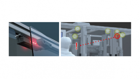
Large And Bright Indicators Show The Open/Closed Conditions Of All Equipment Doors
The SG-P features large, bright, easy-to-see indicators located on both the front and the rear side of the switch body, ensuring high visibility and allowing visual confirmation of the safety state from multiple viewing angles.
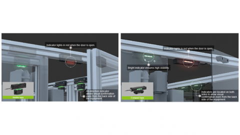
Two Types To Choose From: Visible Type And Compact Type
The Visible type SG-P features the industry's first "Indicator Light Pass-through System", which allows the light from the switch body to pass through the actuator for enhanced visibility.
The Compact type SG-P offers a slim, small profile actuator ideal for mounting onto frameless doors.
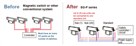
Master-Slave Configuration Structure For Simplified Wiring
The SG-P Series standard unit serves as the master unit and outputs the safety signals (OSSD 1 & 2) in a batch. No extra wiring is required for a cascade connection of the SG-P series sub units (slave units), and up to 30 sub units can be connected to a single standard unit without the need for a dedicated controller.
Compliant With ISO 14119 International Safety Standard (High-Code Model Only)
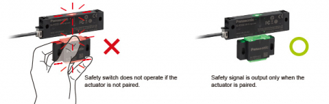
The SG-P Series high-code models are designed to detect only specifically paired actuators and support the ISO 14119 coding level (High Level Coded Actuator) to prevent intentional deactivation of the safety switches.