Exclusive Control Unit for Safety Light Curtain SF-C10
The safety control unit allows the user to connect and control various machine safety components. The SF-C10 series was specifically designed to connect and control Panasonic light curtains, while the SF-C21 safety control unit can be used for a variety of safety devices such as; safety switches, emergency switches, enable grip switches, safety beam sensors, safety scanners, and safety light curtains.
Exclusive Control Unit for Safety Light Curtain SF-C10
Part number list
Results 6
Models table for series Exclusive Control Unit for Safety Light Curtain SF-C10
Part No.
Datasheet
Connectable Safety Light Curtains
Applicable Standards: International Standard
CE Marking Directive Compliance
Control Category
Applicable Standards: Japan
Applicable Standards: Europe (EU)
Applicable Standards: North America
Power Voltage
Current Consumption
Fuse Rating
Safety Output
Safety Output: Application Category
Safety Output: Rated Operation Voltage (Ue)/Rated Operation Current (le)
EN 61496-1 (Type 4), EN 55011, EN ISO 13849-1 (Category 4, PLe), IEC 61496-1 (Type 4), ISO 13849-1 (Category 4, PLe)(Note:SF-C11 and SF-C13 comply with UL 1998 (Class 2).)
ANSI/UL 61496-1 (Type 4), UL 1998 (Class 2) (Note:SF-C11 and SF-C13 comply with UL 1998 (Class 2).)
24 V DC ±10 % Ripple P-P 10 % or less
100 mA or less (without light curtain)
Built-in electronic fuse, Triggering current: 0.5 A or more, Reset after power down
NO contact × 2 (13-14, 23-24)
AC-15, DC-13 (IEC 60947-5-1)
1 A / 24 V DC, resistive load (For inductive load, during contact protection) Min. applicable load: 15 mA (at 24 V DC)
AgNiO + 0.2 micro m 0.008 mil Au plating, self cleaning, positively driven
50 mOhm or less (initial value)
3 A (slow blow)
10,000,000 times or more (open/close frequency of 180 times/min) (Note:The life expectancy of the relay varies depending on the type of load, open / close frequency, ambient conditions and others.)
100,000 times or more (open/close frequency of 20 times/min, 230 V AC, 3 A, using resistance load) (Note:The life expectancy of the relay varies depending on the type of load, open / close frequency, ambient conditions and others.)
30 V DC / 3 A, Min. applicable load: 15 mA (at 24 V DC)
3 A (slow blow)
-
-
III
Green LED (lights up when the power is ON)
Green LED (lights up when safety output is closed) (Note:The operation indicator is marked as "Enabling" on the unit for SF-C12.)
-
Orange LED (lights up when two safety light curtain input polarity selection switch settings are different)
Incorporated (Note:Terminals for utilizing the functions of the SF4B / SF4B-G series are available.)
Incorporated
Incorporated (Sliding switch allows selection of plus/minus ground)
Minus ground: Correspond to PNP output safety light curtain
Plus ground: Correspond to NPN output safety light curtain (Note:Please switch the sliding switch to the PNP side for minus ground and to the NPN side for plus ground.)
2
IP65
-10 to +55 ℃ +14 to +131 ℉
(No dew condensation or icing allowed),
Storage: -25 to +70 ℃ -13 to +158℉
35 to 85 % RH, Storage: 35 to 85 % RH
Resistance 10 to 55 Hz frequency, 0.75 mm 0.030 in amplitude
in X, Y, and Z directions for two hours each
Die-cast aluminium
European terminal
Net weight: 1 kg approx.
CE Marking (Machinery Directive, EMC Directive, RoHS Directive)
EN 61496-1 (Type 4), EN 55011, EN ISO 13849-1 (Category 4, PLe), IEC 61496-1 (Type 4), ISO 13849-1 (Category 4, PLe),
JIS B 9704-1 (Type 4), JIS B 9705-1(Category 4), ANSI/UL 61496-1 (Type 4)
ISO 13849-1 (EN ISO 13849-1, JIS B 9705-1) compliance up to Category 4, PLe standards
JIS B 9704-1 (Type 4), JIS B 9705-1 (Category 4, PLe)
EN 55011, EN ISO 13849-1 (Category 4, PLe)
ANSI/UL 61496-1 (Type 4), UL 1998 (Class 2)
24 V DC plus or minus 10 % Ripple P-P 10 % or less
0.2 A or less (Excluding Safety light curtain and other external connecting device)
PNP open-collector transistor 2 outputs × 3 or NPN open-collector transistor 2 outputs × 3 (selectable using a slider switch)
・Maximum source current: 200 mA
・Applied voltage: same as supply voltage
(between the safety output and +V)
・Residual voltage: 2 V or less (at 200 mA source current)
・Maximum sink current: 200 mA
・Applied voltage: same as supply voltage
(between the safety output and 0 V)
・Residual voltage: 2 V or less (at 200 mA sink current)
Safety output 1: ON when the safety light curtain is in light receiving condition, OFF when the safety light curtain is in light interrupted condition (Note 3)
Safety output 2: ON when the safety light curtain is in light receiving condition or the muting function is valid
OFF when the safety light curtain is in light interrupted condition and the muting function is invalid (Note 3)
Safety output 3: ON when the emergency stop is invalid, OFF when the emergency stop is valid
Incorporated
OFF response: 14 ms or less (Safety output 1 and 2: including the response time of the Safety light curtain) ON response: 90 ms or less (auto-reset) / 140 ms or less (manual reset) (Note) (Note) The auto-reset cannot be used with safety output 3.
PNP open-collector transistor × 3 or NPN open-collector transistor × 3 (selectable using a slider switch)
・Maximum source current: 60 mA
・Applied voltage: same as supply voltage
(between the auxiliary output and +V)
・Residual voltage: 2 V or less (at 60 mA source current)
・Maximum sink current: 60 mA
・Applied voltage: same as supply voltage
(between the auxiliary output and 0 V)
・Residual voltage: 2 V or less (at 60 mA sink current)
Auxiliary output 1: ON when the muting function is invalid, OFF when the muting function is valid
Auxiliary output 2: ON when the override function is invalid, OFF when the override function is valid
Auxiliary output 3: ON when the muting lamp is normal, OFF when the muting lamp is error
Auxiliary output 4: ON when the light curtain is in light interrupted condition, OFF when the light curtain is in light receiving condition (Note:The auxiliary output incorporated in the SF4B series is output.)
Incorporated
Applicable muting lamp: 24 V DC, 3.6 to 30 W (L1, L2 of each unit)
Incorporated
1.66 × 10⁻¹⁰ (Note:Probability of dangerous failure per hour)
100 years or more (Note:Mean time to dangerous failure (in years))
Enclosure: IP40 Terminal: IP20
-10 to +55 ℃ +14 to +131 ℉
(No dew condensation or icing allowed),
Storage: -25 to +70 ℃ -13 to +158 ℉
1,000 V AC for one min. between all supply terminals connected together and enclosure
30 to 85 % RH, Storage: 30 to 95 % RH
20 MOhm , or more, with 500 V DC megger between all supply terminals connected together and enclosure
10 to 55 Hz frequency, 0.35 mm 0.014 in double amplitude in X, Y and Z directions for two hours each
30 G acceleration in X, Y and Z directions three times each
EN 61496-1 (Type 4), EN 55011, EN ISO 13849-1 (Category 4, PLe), IEC 61496-1 (Type 4), ISO 13849-1 (Category 4, PLe)(Note:SF-C11 and SF-C13 comply with UL 1998 (Class 2).)
ANSI/UL 61496-1 (Type 4), UL 1998 (Class 2) (Note:SF-C11 and SF-C13 comply with UL 1998 (Class 2).)
24 V DC ±10 % Ripple P-P 10 % or less
100 mA or less (without safety light curtain)
Built-in electronic fuse, Triggering current: 0.5 A or more, Reset after power down
NO contact × 3 (13-14, 23-24, 33-34)
AC-15, DC-13 (IEC 60947-5-1)
4 A / 30 V DC, 4 A / 230 V AC, resistive load (For inductive load, during contact protection) Min. applicable load: 10 mA (at 24 V DC) (Note:If several SF-C11 or SF-C13 units are being used in a line together, leavea space of 5 mm 0.197 in or more between each unit. If the units are touching each other, reduce the rated operating current for safety output in accordance with the ambient operating temperature as shown in the graphs below.)
AgSnO, self cleaning, positively driven
100 mOhm or less (initial value)
4 A (slow blow)
10,000,000 times or more (open/close frequency of 180 times/min) (Note:The life expectancy of the relay varies depending on the type of load, open / close frequency, ambient conditions and others.)
100,000 times or more (open/close frequency of 20 times/min, 230 V AC, 3 A, using resistance load) (Note:The life expectancy of the relay varies depending on the type of load, open / close frequency, ambient conditions and others.)
24 V DC / 2 A, Min. applicable load: 10 mA (at 24 V DC)
2 A (slow blow)
PNP open‑collector transistor
• Maximum source current: 60 mA
• Applied voltage: same as supply voltage (between the auxiliary output and +V)
• Residual voltage: 2.3 V or less (at 60 mA source current)
• Leakage current: 2 mA or less
ON when the safety light curtain is interrupted
II
Green LED (lights up when the power is ON)
Green LED (lights up when safety output is closed) (Note:The operation indicator is marked as "Enabling" on the unit for SF-C12.)
Yellow LED (lights up when enabling contacts are opened)
Yellow LED (blinks when fault occurs)
Incorporated
Incorporated
Incorporated (Cable connection allows selection of plus/minus ground) Minus ground: Correspond to PNP output safety light curtain Plus ground: Correspond to NPN output safety light curtain (Note):Please switch the sliding switch to the PNP side for minus ground and to the NPN side for plus ground.
2
Enclosure: IP40 Terminal: IP20
-10 to +55 ℃ +14 to +131 ℉ (No dew condensation or icing allowed), Storage: -25 to +70 ℃ -13 to +158℉
30 to 85 % RH, Storage: 30 to 95 % RH
Malfunction resistance 10 to 55Hz, 0.35 mm 0.014 in double amplitude 20 times each in X, Y, and Z directions
ABS
Spring-cage terminal
Net weight: 200 g approx.
CE Marking (Machinery Directive, EMC Directive, RoHS Directive)
EN 61496-1 (Type 4), EN 55011, EN ISO 13849-1 (Category 4, , PLe), IEC 61496-1 (Type 4), ISO 13849-1 (Category 4, PLe), JIS B 9704-1 (Type 4), JIS B 9705-1 (Category 4), ANSI/UL 61496-1 (Type 4), UL 1998 (Class 2)
NO contact × 3 (13-14, 23-24, 33-34)
AC-15, DC-13 (IEC 60947-5-1)
30 V DC / 4 A, 230 V AC / 4 A, resistive load
(For inductive load, during contact protection)
Min. applicable load: 10 mA (at 24 V DC) (Note) : If several SF-C11 or SF-C13 units are being used in a line together, leave a space of 5 mm 0.197 in or more between each unit. If the units are touching each other, reduce the rated operating current for safety output in accordance with the ambient operating temperature as shown in the graphs below.
Silver tin oxide (AgSnO), self cleaning, positively driven
100 mOhm or less (initial value)
4 A (slow blow)
10,000,000 times or more (open/close frequency of 180 times/min) (Note:The life expectancy of the relay varies depending on the type of load, open / close frequency, ambient conditions and others.)
100,000 times or more (open/close frequency of 20 times/min, 230 V AC, 3 A, using resistance load) (Note:The life expectancy of the relay varies depending on the type of load, open / close frequency, ambient conditions and others.)
II
Green LED (lights up when the enabling contacts are closed)
EN 61496-1 (Type 4), EN 55011, EN ISO 13849-1 (Category 4, PLe), ISO 13849-1 (Category 4, PLe)
ANSI/UL 61496-1 (Type 4), UL 1998 (Class 2) (Note:SF-C11 and SF-C13 comply with UL 1998 (Class 2).)
24 V DC ±10 % Ripple P-P 10 % or less
100 mA or less (without safety light curtain)
Built-in electronic fuse, Triggering current: 0.5 A or more, Reset after power down
NO contact × 3 (13-14, 23-24, 33-34)
AC-15, DC-13 (IEC 60947-5-1)
6 A / 30 V DC, 6 A / 230 V AC, resistive load (For inductive load, during contact protection) Min. applicable load: 10 mA (at 24 V DC) (Note:If several SF-C11 or SF-C13 units are being used in a line together, leavea space of 5 mm 0.197 in or more between each unit. If the units are touching each other, reduce the rated operating current for safety output in accordance with the ambient operating temperature as shown in the graphs below.)
AgSnO, self cleaning, positively driven
100 mOhm or less (initial value)
6 A (slow blow)
10,000,000 times or more (open/close frequency of 180 times/min) (Note:The life expectancy of the relay varies depending on the type of load, open / close frequency, ambient conditions and others.)
100,000 times or more (open/close frequency of 20 times/min, 230 V AC, 3 A, using resistance load) (Note:The life expectancy of the relay varies depending on the type of load, open / close frequency, ambient conditions and others.)
24 V DC / 2 A, Min. applicable load: 10 mA (at 24 V DC)
2 A (slow blow)
PNP open-collector transistor • Maximum source current: 60 mA • Applied voltage: same as supply voltage (between the auxiliary output and +V) • Residual voltage: 2.3 V or less (at 60 mA source current) • Leakage current: 2 mA or less
NPN open-collector transistor • Maximum sink current: 60 mA • Applied voltage: same as supply voltage (between the auxiliary output and 0V) • Residual voltage: 1.5 V or less (at 60 mA sink current) • Leakage current: 2 mA or less
Related to auxiliary output of safety light curtain
II
Green LED (lights up when the power is ON)
Green LED (lights up when safety output is closed) (Note:The operation indicator is marked as "Enabling" on the unit for SF-C12.)
Yellow LED (lights up when safety output is opened)
Yellow LED (blinks when fault occurs)
Incorporated
Incorporated
Incorporated (Sliding switch allows selection of plus/minus ground) Minus ground: Correspond to PNP output safety light curtain Plus ground: Correspond to NPN output safety light curtain (Note):Please switch the sliding switch to the PNP side for minus ground and to the NPN side for plus ground.
2
Enclosure: IP40 Terminal: IP20
-10 to +55 ℃ +14 to +131 ℉ (No dew condensation or icing allowed), Storage: -25 to +70 ℃ -13 to +158℉
30 to 85 % RH, Storage: 30 to 95 % RH
Malfunction resistance 10 to 55Hz, 0.35 mm 0.014 in double amplitude 20 times each in X, Y, and Z directions
ABS
Detachable spring-cage terminal
Net weight: 320 g approx.
CE Marking (Machinery Directive, EMC Directive, RoHS Directive)
EN 61496-1 (Type 4), EN 55011, EN ISO 13849-1 (Category 4, , PLe), IEC 61496-1 (Type 4), ISO 13849-1 (Category 4, PLe), JIS B 9704-1 (Type 4), JIS B 9705-1 (Category 4), ANSI/UL 61496-1 (Type 4), UL 1998 (Class 2)
NO contact × 3 (13-14, 23-24, 33-34)
AC-15, DC-13 (IEC 60947-5-1)
30 V DC / 6 A, 230 V AC / 6 A, resistive load(For inductive load, during contact protection)Min. applicable load: 10 mA (at 24 V DC) (Note) : If several SF-C11 or SF-C13 units are being used in a line together, leave a space of 5 mm 0.197 in or more between each unit. If the units are touching each other, reduce the rated operating current for safety output in accordance with the ambient operating temperature as shown in the graphs below.
Silver tin oxide (AgSnO), self cleaning, positively driven
100 mOhm or less (initial value)
6 A (slow blow)
10,000,000 times or more (open/close frequency of 180 times/min) (Note:The life expectancy of the relay varies depending on the type of load, open / close frequency, ambient conditions and others.)
100,000 times or more (open/close frequency of 20 times/min, 230 V AC, 3 A, using resistance load) (Note:The life expectancy of the relay varies depending on the type of load, open / close frequency, ambient conditions and others.)
II
Green LED (lights up when the enabling contacts are closed)
ISO 13849-1 (EN ISO 13849-1, JIS B 9705-1) compliance up to Category 4, PLe standards
JIS B 9704-1 (Type 4), JIS B 9705-1 (Category 4, PLe)
EN 55011, EN ISO 13849-1 (Category 4, PLe)
ANSI/UL 61496-1 (Type 4), UL 1998 (Class 2)
24 V DC plus or minus 10 % Ripple P-P 10 % or less
0.2 A or less (Excluding Safety light curtain and other external connecting device)
PNP open-collector transistor 2 outputs × 3 or NPN open-collector transistor 2 outputs × 3 (selectable using a slider switch)
・Maximum source current: 200 mA
・Applied voltage: same as supply voltage
(between the safety output and +V)
・Residual voltage: 2 V or less (at 200 mA source current)
・Maximum sink current: 200 mA
・Applied voltage: same as supply voltage
(between the safety output and 0 V)
・Residual voltage: 2 V or less (at 200 mA sink current)
Safety output 1: ON when the safety light curtain is in light receiving condition, OFF when the safety light curtain is in light interrupted condition (Note 3)
Safety output 2: ON when the safety light curtain is in light receiving condition or the muting function is valid
OFF when the safety light curtain is in light interrupted condition and the muting function is invalid (Note 3)
Safety output 3: ON when the emergency stop is invalid, OFF when the emergency stop is valid
Incorporated
OFF response: 14 ms or less (Safety output 1 and 2: including the response time of the light curtain) ON response: 90 ms or less (auto-reset) / 140 ms or less (manual reset) (Note) (Note) The auto-reset cannot be used with safety output 3.
PNP open-collector transistor × 3 or NPN open-collector transistor × 3 (selectable using a slider switch)
・Maximum source current: 60 mA
・Applied voltage: same as supply voltage
(between the auxiliary output and +V)
・Residual voltage: 2 V or less (at 60 mA source current)
・Maximum sink current: 60 mA
・Applied voltage: same as supply voltage
(between the auxiliary output and 0 V)
・Residual voltage: 2 V or less (at 60 mA sink current)
Auxiliary output 1: ON when the muting function is invalid, OFF when the muting function is valid
Auxiliary output 2: ON when the override function is invalid, OFF when the override function is valid
Auxiliary output 3: ON when the muting lamp is normal, OFF when the muting lamp is error
Auxiliary output 4: ON when the light curtain is in light interrupted condition, OFF when the light curtain is in light receiving condition (Note:The auxiliary output incorporated in the SF4B series is output.)
Incorporated
Applicable muting lamp: 24 V DC, 3.6 to 30 W (L1, L2 of each unit)
Incorporated
1.66 × 10⁻¹⁰ (Note:Probability of dangerous failure per hour)
100 years or more (Note:Mean time to dangerous failure (in years))
Enclosure: IP40 Terminal: IP20
-10 to +55 ℃ +14 to +131 ℉
(No dew condensation or icing allowed),
Storage: -25 to +70 ℃ -13 to +158 ℉
1,000 V AC for one min. between all supply terminals connected together and enclosure
30 to 85 % RH, Storage: 30 to 95 % RH
20 MOhm , or more, with 500 V DC megger between all supply terminals connected together and enclosure
10 to 55 Hz frequency, 0.35 mm 0.014 in double amplitude in X, Y and Z directions for two hours each
30 G acceleration in X, Y and Z directions three times each
Enclosure: ABS
Detachable spring-cage terminal
Net weight: 250 g approx.
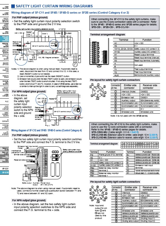
I/O Circuit and Wiring diagrams
Wiring diagram of SF-C11 and SF4B / SF4B-G series or SF2B series