| | 32 points (Input: 16, Output: 16), When expanded: Max. 384 points | Relay symbol / Cyclic operation | Built-in flash ROM (no backup battery required) | 120 types approx. | 270 types approx. | 24 k /32 k /40 k / 64 k steps
Can be selected at system register No. 0
When the program capacity is changed, the number of words that can be used in the data register (DT) is also changed.
| Program capacity |
DT Number of word |
24k steps
32k steps(initial value)
40k steps
64k steps |
65,533 words
32,765 words(initial value)
24,573 words
12,285 words |
| Basic instruction (NOT: /) : 10 ns/step approx. (Up to 10 k steps) ,0.18 μs/step approx. (10 k steps and later)
Basic instruction (ST) : 40 ns/step approx. (Up to 10 k steps) ,0.65 μs/step approx. (10 k steps and later)
High-level instruction (FOMV) : 0.14 μs/step approx. (Up to 10 k steps) , 1.2 μs/step approx. (10 k steps and later) | Control unit: 100 μs or less approx. and FP0 / FP0R expanshion unit refresh time (Note)
Note : Refresh times for FP0 / FP0R expansion units
8 points unit : Number of units×0.8ms
16 points unit : Number of units×1.0ms
32 points unit : Number of units×1.3ms
64 points unit : Number of units×1.9ms | 1, 760 points (X0 to X109F)(Note 1, 2)
Note 1 : The number of points that can be used depends on the combination of hardware.
Note 2 : Some specifications are compatible with FPΣ. | 1, 760 points (X0 to X109F)(Note 1, 2)
Note 1 : The number of points that can be used depends on the combination of hardware.
Note 2 : Some specifications are compatible with FPΣ. | 8,192 points (R0 to R511F) (Note 1)
Note 1 : Some specifications are compatible with FPΣ. | 800 points (R9000 to R951F) | 1,024 points (initial setting, timer: 1,008 points, counter: 16 points)(Note)
Note : An auxiliary timer instruction (F137) can be used to add the number of points. | 2,048 points (L0 to L127F) | 12,285 words or 24,573 words or 32,765 words or 65,533 words(Note)
Note : System register No. 0 (program capacity) can be configured to select the capacity of the data register (DT). | 1,000 words (DT90000 to DT90999)(Note)
Note : Some specifications are compatible with FPΣ. | 256 words (LD0 to LD255) | 14 words (I0 to ID) | Points for the program capacity | 256 points | 256 points | 1,000 stages | 500 subroutines | 9 programs
•Input: 8 programs (INT0 to INT7)
•Periodic: 1 program (INT24) | Available(Note)
[Sampling by commands / Sampling at regular time intervals (For one sampling: 16 bits + 3 words), 1,000 samples]
Note : Logging trace and sampling trace cannot be used at the same time. | I/O comments, remarks and block comments can be stored.
(no backup battery required, 1 M byte) | Max. 16 units, link relays: 1,024 points, link registers: 128 words.
(Data transfer and remote programming are not supported) | Available (32 digits) | Available | Available | Watchdog timer, program syntax check, etc. | Available | SD memory card project copy,
Logging trace function (Note)
SD memory card access instruction,
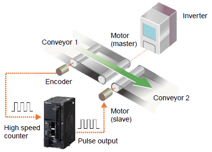
Note : Logging trace and sampling trace cannot be used at the same time. | Available [Built-in memory (ROM ⇔ RAM)] | Single-phase 4 channels (Max. 100 kHz each input) or 2-phase 2 channels (Max. 50 kHz each input)(Note)
Note : The specifications are based on the rated input voltage of 24 V DC at +25 ℃ +77 ℉. The maximum operation frequency may be lower depending on the applied voltage, ambient temperature, and conditions of use. The maximum operation frequency varies depending on how the unit is used. | 4 channels (Max. 100 kHz each axis)(Note)
Note : The specifications are based on the rated input voltage of 24 V DC at +25 ℃ +77 ℉. The maximum operation frequency may be lower depending on the applied voltage, ambient temperature, and conditions of use. The maximum operation frequency varies depending on how the unit is used. | 4 channels (1 Hz to 70 kHz: 1,000 resolution / 70.001 kHz to 100 kHz: 100 resolution(Note)
Note : The specifications are based on the rated input voltage of 24 V DC at +25 ℃ +77 ℉. The maximum operation frequency may be lower depending on the applied voltage, ambient temperature, and conditions of use. The maximum operation frequency varies depending on how the unit is used. | Total 8 points (with high speed counter) | 0.1 ms to 30 sec. | Not available | Year (last two digits), month, day, hour (24-hour display), minute, second and day of week(Note 1, 2)
Note 1 : Accuracy of the clock / calendar (within ± 90 seconds per month at +25 ℃ +77 ℉).If an error of the clock / calendar becomes a problem in the system, set an accurate time periodically.
Note 2 : If the battery is not attached, calendar information is cleared when the power is turned off. It will be necessary to set the date when the power is turned on. | Data register: all area(Note)
Note : Data can be rewritten up to 10,000 times. Hold / non-hold areas can be specified in the system registers. | Counter: 16 points
Internal relay: 128 points
Data register: 315 words
Note : Data can be rewritten up to 10,000 times. Hold / non-hold areas can be specified in the system registers. | Hold areas or non-hold areas can be specified by setting the system registers
No.6 to No. 13. (It is also possible to make the setting for hold all points.) | 5 years or more under a production condition (operates for 8 hours per day) | EMC Directive, RoHS Directive | 24 V DC | 20.4 to 28.8 V DC | 170 mA or less | 4 ms (at 20.4 V DC), 10 ms (24 V DC or higher) | 0 to +55 ℃ +32 to +131 ℉, At storage: -40 to +70 ℃ - 40 to +158 ℉ | 10 to 95 % RH (at +25 ℃ +77 ℉, no dew condensation allowed), At storage: 10 to 95 % RH (at +25 ℃ +77 ℉, no dew condensation allowed) | (Detection current: 5 mA)
500 V AC for 1 minute
Input and output terminals ⇔ power and functional ground terminals
Input terminals ⇔ Output terminals | (Test voltage: 500 V DC)
100 MΩ or more
Input and output terminals ⇔ power and functional ground terminals
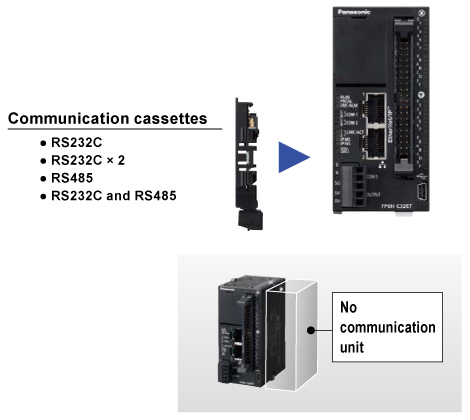
Input terminals ⇔ Output terminals | 5 to 8.4 Hz, single amplitude of 3.5 mm 0.138 in, 8.4 to 150 Hz, constant acceleration of 9.8 m/s2, for 10 times each in X, Y, and Z directions (1 octave/min.) (JIS B 3502, IEC 61131-2) | 147 m/s2, 4 times each in X, Y, and Z directions (JIS B 3502, IEC 61131-2) | 1,000 V (p-p) with pulse widths 50 ns and 1 μs (using a noise simulator) (Power supply terminal) | Free from corrosive gasses and excessive dust | Category II | Pollution level 2 | 130 g approx. | RS-232C, three-wire system, 1 channel (Not insulated) | 15 m 49.213 ft | 1 : 1 communication | Half-duplex system | Start-stop synchronization system | Multi-conductor shielded wire | 1,200(Note), 2,400(Note), 4,800, 9,600, 19,200, 38,400, 57,600, 115,200, 230,400 bits/sec.
Note : System register no. 415 cannot be used to set the baud rate to 1,200 bps. To set the baud rate to 1,200 bps, use the SYS1 instruction. If the baud rate of any of the COM ports is 2,400 bps or lower, F-ROM access will slow down.
Example) F12(ICRD) instruction, P13(ICWT) instruction, etc. | 7 bits / 8 bits | none / odd / even | 1 bit / 2 bits | with STX / without STX | CR / CR + LF / none / ETX / Time (0 to 100.00 ms) | Transmit from bit 0 in character units | MEWTOCOL-COM (Master / Slave) (Computer link)
General-purpose communication
PLC link
MODBUS RTU (Master / Slave) | The start and end codes can be used only for general-purpose serial communications.
The unit No. (station number) can be selected at system register No. 410. | Ethernet 100BASE-TX / 10BASE-T | 100 Mbps, 10 Mbps auto negotiation function | 100 m 328.084 ft (500 m 1640.420 ft when a repeater is used) | Max. 10 (system connection: 1, user connection: 9) | Full duplex / Half-duplex system | TCP / IP, UDP | Supports name servers | Automatic IP address acquisition | File transmission, server function, No. of users:1
Client function, Data file transfer | Time adjustment function | 4 kB / 1 connection (user connection: 1 to 9) (Note)
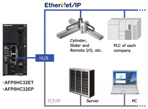
Note : General-purpose communications can be up to 4 kB (reception) and up to 2 kB (transmission) per connection. | EtherNet/IP
MEWTOCOL-COM (Master / Slave) (Computer link)
MODBUS-TCP (Master / Slave)
MEWTOCOL-DAT (Master / Slave)
General-purpose communication
MC protocol (Note 1) (Master / Slave)
Note : MC protocol is a short form denoting MELSEC communication protocol; MELSEC is a registered trademark of Mitsubishi Electric Corporation.QnA compatible 3E frame, only binary (bulk writing and bulk reading) use is available. | USB2.0 Full speed (USB mini B type) | Computer link (slave) | Connecting programmable display model : For 5 V DC type GT02 series Programmable Display | 24 V DC | 21.6 to 26.4 V DC | High-speed part (X0 to X7) : 8 mA approx.
Low-speed part (X8 to XF) : 3.5 mA approx. | 16 points/common (Y0 to YF / 1 common) | High-speed part (X0 to X7) : 19.2 V DC / 6 mA
Low-speed part (X8 to XF) : 19.2 V DC / 3 mA | 2.4 V DC / 1 mA | High-speed part (X0 to X7) : 3 kΩ approx.
Low-speed part (X8 to XF) : 6.8 kΩ approx. | High-speed part (For Y0, Y1, Y3, Y4, Y8, Y9, YB, YC) : 2 μs or less,
Low-speed part (For Y2, Y5, Y6, Y7, YA, YD, YE, YF) : 1 ms or less | High-speed part (For Y0, Y1, Y3, Y4, Y8, Y9, YB, YC) : 5 μs or less,
Low-speed part (For Y2, Y5, Y6, Y7, YA, YD, YE, YF) : 1 ms or less | LED display | Pch open drain | 24 V DC | 21.6 to 26.4 V DC | 0.3 A (For Y0 to YF) | High-speed part (For Y0, Y1, Y3, Y4, Y8, Y9, YB, YC) : 1.0 A,
Low-speed part (For Y2, Y5, Y6, Y7, YA, YD, YE, YF) : 0.5 A | 2 μA or less | 0.5 V DC or less | Provided (automatically protected for each 8 points) | Zener diode | LED display |
| | 32 points (Input: 16, Output: 16), When expanded: Max. 384 points | Relay symbol / Cyclic operation | Built-in flash ROM (no backup battery required) | 120 types approx. | 270 types approx. | 24 k /32 k /40 k / 64 k steps
Can be selected at system register No. 0
When the program capacity is changed, the number of words that can be used in the data register (DT) is also changed.
| Program capacity |
DT Number of word |
24k steps
32k steps(initial value)
40k steps
64k steps |
65,533 words
32,765 words(initial value)
24,573 words
12,285 words |
| Basic instruction (NOT: /) : 10 ns/step approx. (Up to 10 k steps) ,0.18 μs/step approx. (10 k steps and later)
Basic instruction (ST) : 40 ns/step approx. (Up to 10 k steps) ,0.65 μs/step approx. (10 k steps and later)
High-level instruction (FOMV) : 0.14 μs/step approx. (Up to 10 k steps) , 1.2 μs/step approx. (10 k steps and later) | Control unit: 100 μs or less approx. and FP0 / FP0R expanshion unit refresh time (Note)
Note : Refresh times for FP0 / FP0R expansion units
8 points unit : Number of units×0.8ms
16 points unit : Number of units×1.0ms
32 points unit : Number of units×1.3ms
64 points unit : Number of units×1.9ms | 1, 760 points (X0 to X109F)(Note 1, 2)
Note 1 : The number of points that can be used depends on the combination of hardware.
Note 2 : Some specifications are compatible with FPΣ. | 1, 760 points (X0 to X109F)(Note 1, 2)
Note 1 : The number of points that can be used depends on the combination of hardware.
Note 2 : Some specifications are compatible with FPΣ. | 8,192 points (R0 to R511F) (Note 1)
Note 1 : Some specifications are compatible with FPΣ. | 800 points (R9000 to R951F) | 1,024 points (initial setting, timer: 1,008 points, counter: 16 points)(Note)
Note : An auxiliary timer instruction (F137) can be used to add the number of points. | 2,048 points (L0 to L127F) | 12,285 words or 24,573 words or 32,765 words or 65,533 words(Note)
Note : System register No. 0 (program capacity) can be configured to select the capacity of the data register (DT). | 1,000 words (DT90000 to DT90999)(Note)
Note : Some specifications are compatible with FPΣ. | 256 words (LD0 to LD255) | 14 words (I0 to ID) | Points for the program capacity | 256 points | 256 points | 1,000 stages | 500 subroutines | 9 programs
•Input: 8 programs (INT0 to INT7)
•Periodic: 1 program (INT24) | Available(Note)
[Sampling by commands / Sampling at regular time intervals (For one sampling: 16 bits + 3 words), 1,000 samples]
Note : Logging trace and sampling trace cannot be used at the same time. | I/O comments, remarks and block comments can be stored.
(no backup battery required, 1 M byte) | Max. 16 units, link relays: 1,024 points, link registers: 128 words.
(Data transfer and remote programming are not supported) | Available (32 digits) | Available | Available | Watchdog timer, program syntax check, etc. | Available | SD memory card project copy,
Logging trace function (Note)
SD memory card access instruction,
Note : Logging trace and sampling trace cannot be used at the same time. | Available [Built-in memory (ROM ⇔ RAM)] | Single-phase 4 channels (Max. 100 kHz each input) or 2-phase 2 channels (Max. 50 kHz each input)(Note)
Note : The specifications are based on the rated input voltage of 24 V DC at +25 ℃ +77 ℉. The maximum operation frequency may be lower depending on the applied voltage, ambient temperature, and conditions of use. The maximum operation frequency varies depending on how the unit is used. | 4 channels (Max. 100 kHz each axis)(Note)
Note : The specifications are based on the rated input voltage of 24 V DC at +25 ℃ +77 ℉. The maximum operation frequency may be lower depending on the applied voltage, ambient temperature, and conditions of use. The maximum operation frequency varies depending on how the unit is used. | 4 channels (1 Hz to 70 kHz: 1,000 resolution / 70.001 kHz to 100 kHz: 100 resolution(Note)
Note : The specifications are based on the rated input voltage of 24 V DC at +25 ℃ +77 ℉. The maximum operation frequency may be lower depending on the applied voltage, ambient temperature, and conditions of use. The maximum operation frequency varies depending on how the unit is used. | Total 8 points (with high speed counter) | 0.1 ms to 30 sec. | Not available | Year (last two digits), month, day, hour (24-hour display), minute, second and day of week(Note 1, 2)
Note 1 : Accuracy of the clock / calendar (within ± 90 seconds per month at +25 ℃ +77 ℉).If an error of the clock / calendar becomes a problem in the system, set an accurate time periodically.
Note 2 : If the battery is not attached, calendar information is cleared when the power is turned off. It will be necessary to set the date when the power is turned on. | Data register: all area(Note)
Note : Data can be rewritten up to 10,000 times. Hold / non-hold areas can be specified in the system registers. | Counter: 16 points
Internal relay: 128 points
Data register: 315 words
Note : Data can be rewritten up to 10,000 times. Hold / non-hold areas can be specified in the system registers. | Hold areas or non-hold areas can be specified by setting the system registers
No.6 to No. 13. (It is also possible to make the setting for hold all points.) | 5 years or more under a production condition (operates for 8 hours per day) | EMC Directive, RoHS Directive | 24 V DC | 20.4 to 28.8 V DC | 170 mA or less | 4 ms (at 20.4 V DC), 10 ms (24 V DC or higher) | 0 to +55 ℃ +32 to +131 ℉, At storage: -40 to +70 ℃ - 40 to +158 ℉ | 10 to 95 % RH (at +25 ℃ +77 ℉, no dew condensation allowed), At storage: 10 to 95 % RH (at +25 ℃ +77 ℉, no dew condensation allowed) | (Detection current: 5 mA)
500 V AC for 1 minute
Input and output terminals ⇔ power and functional ground terminals
Input terminals ⇔ Output terminals | (Test voltage: 500 V DC)
100 MΩ or more
Input and output terminals ⇔ power and functional ground terminals
Input terminals ⇔ Output terminals | 5 to 8.4 Hz, single amplitude of 3.5 mm 0.138 in, 8.4 to 150 Hz, constant acceleration of 9.8 m/s2, for 10 times each in X, Y, and Z directions (1 octave/min.) (JIS B 3502, IEC 61131-2) | 147 m/s2, 4 times each in X, Y, and Z directions (JIS B 3502, IEC 61131-2) | 1,000 V (p-p) with pulse widths 50 ns and 1 μs (using a noise simulator) (Power supply terminal) | Free from corrosive gasses and excessive dust | Category II | Pollution level 2 | 130 g approx. | RS-232C, three-wire system, 1 channel (Not insulated) | 15 m 49.213 ft | 1 : 1 communication | Half-duplex system | Start-stop synchronization system | Multi-conductor shielded wire | 1,200(Note), 2,400(Note), 4,800, 9,600, 19,200, 38,400, 57,600, 115,200, 230,400 bits/sec.
Note : System register no. 415 cannot be used to set the baud rate to 1,200 bps. To set the baud rate to 1,200 bps, use the SYS1 instruction. If the baud rate of any of the COM ports is 2,400 bps or lower, F-ROM access will slow down.
Example) F12(ICRD) instruction, P13(ICWT) instruction, etc. | 7 bits / 8 bits | none / odd / even | 1 bit / 2 bits | with STX / without STX | CR / CR + LF / none / ETX / Time (0 to 100.00 ms) | Transmit from bit 0 in character units | MEWTOCOL-COM (Master / Slave) (Computer link)
General-purpose communication
PLC link
MODBUS RTU (Master / Slave) | The start and end codes can be used only for general-purpose serial communications.
The unit No. (station number) can be selected at system register No. 410. | Ethernet 100BASE-TX / 10BASE-T | 100 Mbps, 10 Mbps auto negotiation function | 100 m 328.084 ft (500 m 1640.420 ft when a repeater is used) | Max. 10 (system connection: 1, user connection: 9) | Full duplex / Half-duplex system | TCP / IP, UDP | Supports name servers | Automatic IP address acquisition | File transmission, server function, No. of users:1
Client function, Data file transfer | Time adjustment function | 4 kB / 1 connection (user connection: 1 to 9) (Note)
Note : General-purpose communications can be up to 4 kB (reception) and up to 2 kB (transmission) per connection. | EtherNet/IP
MEWTOCOL-COM (Master / Slave) (Computer link)
MODBUS-TCP (Master / Slave)
MEWTOCOL-DAT (Master / Slave)
General-purpose communication
MC protocol (Note 1) (Master / Slave)
Note : MC protocol is a short form denoting MELSEC communication protocol; MELSEC is a registered trademark of Mitsubishi Electric Corporation.QnA compatible 3E frame, only binary (bulk writing and bulk reading) use is available. | USB2.0 Full speed (USB mini B type) | Computer link (slave) | Connecting programmable display model : For 5 V DC type GT02 series Programmable Display | 24 V DC | 21.6 to 26.4 V DC | High-speed part (X0 to X7) : 8 mA approx.
Low-speed part (X8 to XF) : 3.5 mA approx. | 16 points/common (Y0 to YF / 1 common) | High-speed part (X0 to X7) : 19.2 V DC / 6 mA
Low-speed part (X8 to XF) : 19.2 V DC / 3 mA | 2.4 V DC / 1 mA | High-speed part (X0 to X7) : 3 kΩ approx.
Low-speed part (X8 to XF) : 6.8 kΩ approx. | High-speed part (For Y0, Y1, Y3, Y4, Y8, Y9, YB, YC) : 2 μs or less,
Low-speed part (For Y2, Y5, Y6, Y7, YA, YD, YE, YF) : 1 ms or less | High-speed part (For Y0, Y1, Y3, Y4, Y8, Y9, YB, YC) : 5 μs or less,
Low-speed part (For Y2, Y5, Y6, Y7, YA, YD, YE, YF) : 1 ms or less | LED display | Nch open drain | 5 to 24 V DC | 4.75 to 26.4 V DC | 0.3 A (For Y0, Y1, Y3, Y4, Y8,Y9, YB,YC),
0.1 A (For Y2, Y5, Y6, Y7, YA, YD, YE, YF) | High-speed part (For Y0, Y1, Y3, Y4, Y8, Y9, YB, YC) : 1.0 A,
Low-speed part (For Y2, Y5, Y6, Y7, YA, YD, YE, YF) : 0.5 A | 1 μA or less | 0.5 V DC or less | Provided (automatically protected for each 8 points) | Zener diode | LED display |
| | 32 points (Input: 16, Output: 16), When expanded: Max. 384 points | Relay symbol / Cyclic operation | Built-in flash ROM (no backup battery required) | 120 types approx. | 240 types approx. | 24 k /32 k steps
Can be selected at system register No. 0
When the program capacity is changed, the number of words that can be used in the data register (DT) is also changed.
| Program capacity |
DT Number of word |
24k steps
32k steps(initial value) |
65,533 words
32,765 words(initial value) |
| Basic instruction (NOT: /) : 10 ns/step approx. (Up to 10 k steps) ,0.18 μs/step approx. (10 k steps and later)
Basic instruction (ST) : 40 ns/step approx. (Up to 10 k steps) ,0.65 μs/step approx. (10 k steps and later)
High-level instruction (FOMV) : 0.14 μs/step approx. (Up to 10 k steps) , 1.2 μs/step approx. (10 k steps and later) | Control unit: 40 μs or less approx. and FP0 / FP0R expanshion unit refresh time (Note)
Note : Refresh times for FP0 / FP0R expansion units
8 points unit : Number of units×0.8ms
16 points unit : Number of units×1.0ms
32 points unit : Number of units×1.3ms
64 points unit : Number of units×1.9ms | 1, 760 points (X0 to X109F)(Note 1, 2)
Note 1 : The number of points that can be used depends on the combination of hardware.
Note 2 : Some specifications are compatible with FPΣ. | 1, 760 points (X0 to X109F)(Note 1, 2)
Note 1 : The number of points that can be used depends on the combination of hardware.
Note 2 : Some specifications are compatible with FPΣ. | 4,096 points (R0 to R255F) or 8,192 points (R0 to R511F) (Note 1,2)
Note 1 : Some specifications are compatible with FPΣ.
Note 2 : System register No. 1 (internal relay capacity) can be configured to select "0: 4,096 points / 1: 8,192 points". | 800 points (R9000 to R951F) | 1,024 points (initial setting, timer: 1,008 points, counter: 16 points)(Note)
Note : An auxiliary timer instruction (F137) can be used to add the number of points. | 2,048 points (L0 to L127F) | 32,765 words or 65,533 words(Note)
Note : System register No. 0 (program capacity) can be configured to select the capacity of the data register (DT). | 1,000 words (DT90000 to DT90999)(Note)
Note : Some specifications are compatible with FPΣ. | 256 words (LD0 to LD255) | 14 words (I0 to ID) | Points for the program capacity | 256 points | 256 points | 1,000 stages | 500 subroutines | 9 programs
•Input: 8 programs (INT0 to INT7)
•Periodic: 1 program (INT24) | Available(Note)
[Sampling by commands / Sampling at regular time intervals (For one sampling: 16 bits + 3 words), 1,000 samples]
Note : Logging trace and sampling trace cannot be used at the same time. | I/O comments, remarks and block comments can be stored.
(no backup battery required, 1 M byte) | Max. 16 units, link relays: 1,024 points, link registers: 128 words.
(Data transfer and remote programming are not supported) | Available (32 digits) | Available | Available | Watchdog timer, program syntax check, etc. | Available | - | Available [Built-in memory (ROM ⇔ RAM)] | Single-phase 4 channels (Max. 100 kHz each input) or 2-phase 2 channels (Max. 50 kHz each input)(Note)
Note : The specifications are based on the rated input voltage of 24 V DC at +25 ℃ +77 ℉. The maximum operation frequency may be lower depending on the applied voltage, ambient temperature, and conditions of use. The maximum operation frequency varies depending on how the unit is used. | 4 channels (Max. 100 kHz each axis)(Note)
Note : The specifications are based on the rated input voltage of 24 V DC at +25 ℃ +77 ℉. The maximum operation frequency may be lower depending on the applied voltage, ambient temperature, and conditions of use. The maximum operation frequency varies depending on how the unit is used. | 4 channels (1 Hz to 70 kHz: 1,000 resolution / 70.001 kHz to 100 kHz: 100 resolution(Note)
Note : The specifications are based on the rated input voltage of 24 V DC at +25 ℃ +77 ℉. The maximum operation frequency may be lower depending on the applied voltage, ambient temperature, and conditions of use. The maximum operation frequency varies depending on how the unit is used. | Total 8 points (with high speed counter) | 0.1 ms to 30 sec. | 2 channels (0 to 4000) | Year (last two digits), month, day, hour (24-hour display), minute, second and day of week(Note 1, 2)
Note 1 : Accuracy of the clock / calendar (within ± 90 seconds per month at +25 ℃ +77 ℉).If an error of the clock / calendar becomes a problem in the system, set an accurate time periodically.
Note 2 : If the battery is not attached, calendar information is cleared when the power is turned off. It will be necessary to set the date when the power is turned on. | Data register: all area(Note)
Note : Data can be rewritten up to 10,000 times. Hold / non-hold areas can be specified in the system registers. | Counter: 16 points
Internal relay: 128 points
Data register: 315 words
Note : Data can be rewritten up to 10,000 times. Hold / non-hold areas can be specified in the system registers. | Hold areas or non-hold areas can be specified by setting the system registers
No.6 to No. 13. (It is also possible to make the setting for hold all points.) | 5 years or more under a production condition (operates for 8 hours per day) | EMC Directive, RoHS Directive | 24 V DC | 20.4 to 28.8 V DC | 140 mA or less | 4 ms (at 20.4 V DC), 10 ms (24 V DC or higher) | 0 to +55 ℃ +32 to +131 ℉, At storage: -40 to +70 ℃ - 40 to +158 ℉ | 10 to 95 % RH (at +25 ℃ +77 ℉, no dew condensation allowed), At storage: 10 to 95 % RH (at +25 ℃ +77 ℉, no dew condensation allowed) | (Detection current: 5 mA)
500 V AC for 1 minute
Input and output terminals ⇔ power and functional ground terminals
Input terminals ⇔ Output terminals | (Test voltage: 500 V DC)
100 MΩ or more
Input and output terminals ⇔ power and functional ground terminals
Input terminals ⇔ Output terminals | 5 to 8.4 Hz, single amplitude of 3.5 mm 0.138 in, 8.4 to 150 Hz, constant acceleration of 9.8 m/s2, for 10 times each in X, Y, and Z directions (1 octave/min.) (JIS B 3502, IEC 61131-2) | 147 m/s2, 4 times each in X, Y, and Z directions (JIS B 3502, IEC 61131-2) | 1,000 V (p-p) with pulse widths 50 ns and 1 μs (using a noise simulator) (Power supply terminal) | Free from corrosive gasses and excessive dust | Category II | Pollution level 2 | 110 g approx. | RS-232C, three-wire system, 1 channel (Not insulated) | 15 m 49.213 ft | 1 : 1 communication | Half-duplex system | Start-stop synchronization system | Multi-conductor shielded wire | 1,200(Note), 2,400(Note), 4,800, 9,600, 19,200, 38,400, 57,600, 115,200, 230,400 bits/sec.
Note : System register no. 415 cannot be used to set the baud rate to 1,200 bps. To set the baud rate to 1,200 bps, use the SYS1 instruction. If the baud rate of any of the COM ports is 2,400 bps or lower, F-ROM access will slow down.
Example) F12(ICRD) instruction, P13(ICWT) instruction, etc. | 7 bits / 8 bits | none / odd / even | 1 bit / 2 bits | with STX / without STX | CR / CR + LF / none / ETX / Time (0 to 100.00 ms) | Transmit from bit 0 in character units | MEWTOCOL-COM (Master / Slave) (Computer link)
General-purpose communication
PLC link
MODBUS RTU (Master / Slave) | The start and end codes can be used only for general-purpose serial communications.
The unit No. (station number) can be selected at system register No. 410. | | | | | | | | | | | | | USB2.0 Full speed (USB mini B type) | Computer link (slave) | Connecting programmable display model : For 5 V DC type GT02 series Programmable Display | 24 V DC | 21.6 to 26.4 V DC | High-speed part (X0 to X7) : 8 mA approx.
Low-speed part (X8 to XF) : 3.5 mA approx. | 16 points/common (Y0 to YF / 1 common) | High-speed part (X0 to X7) : 19.2 V DC / 6 mA
Low-speed part (X8 to XF) : 19.2 V DC / 3 mA | 2.4 V DC / 1 mA | High-speed part (X0 to X7) : 3 kΩ approx.
Low-speed part (X8 to XF) : 6.8 kΩ approx. | High-speed part (For Y0, Y1, Y3, Y4, Y8, Y9, YB, YC) : 2 μs or less,
Low-speed part (For Y2, Y5, Y6, Y7, YA, YD, YE, YF) : 1 ms or less | High-speed part (For Y0, Y1, Y3, Y4, Y8, Y9, YB, YC) : 5 μs or less,
Low-speed part (For Y2, Y5, Y6, Y7, YA, YD, YE, YF) : 1 ms or less | LED display | Pch open drain | 24 V DC | 21.6 to 26.4 V DC | 0.3 A (For Y0 to YF) | High-speed part (For Y0, Y1, Y3, Y4, Y8, Y9, YB, YC) : 1.0 A,
Low-speed part (For Y2, Y5, Y6, Y7, YA, YD, YE, YF) : 0.5 A | 2 μA or less | 0.5 V DC or less | Provided (automatically protected for each 8 points) | Zener diode | LED display |
| | 32 points (Input: 16, Output: 16), When expanded: Max. 384 points | Relay symbol / Cyclic operation | Built-in flash ROM (no backup battery required) | 120 types approx. | 240 types approx. | 24 k /32 k steps
Can be selected at system register No. 0
When the program capacity is changed, the number of words that can be used in the data register (DT) is also changed.
| Program capacity |
DT Number of word |
24k steps
32k steps(initial value) |
65,533 words
32,765 words(initial value) |
| Basic instruction (NOT: /) : 10 ns/step approx. (Up to 10 k steps) ,0.18 μs/step approx. (10 k steps and later)
Basic instruction (ST) : 40 ns/step approx. (Up to 10 k steps) ,0.65 μs/step approx. (10 k steps and later)
High-level instruction (FOMV) : 0.14 μs/step approx. (Up to 10 k steps) , 1.2 μs/step approx. (10 k steps and later) | Control unit: 40 μs or less approx. and FP0 / FP0R expanshion unit refresh time (Note)
Note : Refresh times for FP0 / FP0R expansion units
8 points unit : Number of units×0.8ms
16 points unit : Number of units×1.0ms
32 points unit : Number of units×1.3ms
64 points unit : Number of units×1.9ms | 1, 760 points (X0 to X109F)(Note 1, 2)
Note 1 : The number of points that can be used depends on the combination of hardware.
Note 2 : Some specifications are compatible with FPΣ. | 1, 760 points (X0 to X109F)(Note 1, 2)
Note 1 : The number of points that can be used depends on the combination of hardware.
Note 2 : Some specifications are compatible with FPΣ. | 4,096 points (R0 to R255F) or 8,192 points (R0 to R511F) (Note 1,2)
Note 1 : Some specifications are compatible with FPΣ.
Note 2 : System register No. 1 (internal relay capacity) can be configured to select "0: 4,096 points / 1: 8,192 points". | 800 points (R9000 to R951F) | 1,024 points (initial setting, timer: 1,008 points, counter: 16 points)(Note)
Note : An auxiliary timer instruction (F137) can be used to add the number of points. | 2,048 points (L0 to L127F) | 32,765 words or 65,533 words(Note)
Note : System register No. 0 (program capacity) can be configured to select the capacity of the data register (DT). | 1,000 words (DT90000 to DT90999)(Note)
Note : Some specifications are compatible with FPΣ. | 256 words (LD0 to LD255) | 14 words (I0 to ID) | Points for the program capacity | 256 points | 256 points | 1,000 stages | 500 subroutines | 9 programs
•Input: 8 programs (INT0 to INT7)
•Periodic: 1 program (INT24) | Available(Note)
[Sampling by commands / Sampling at regular time intervals (For one sampling: 16 bits + 3 words), 1,000 samples]
Note : Logging trace and sampling trace cannot be used at the same time. | I/O comments, remarks and block comments can be stored.
(no backup battery required, 1 M byte) | Max. 16 units, link relays: 1,024 points, link registers: 128 words.
(Data transfer and remote programming are not supported) | Available (32 digits) | Available | Available | Watchdog timer, program syntax check, etc. | Available | - | Available [Built-in memory (ROM ⇔ RAM)] | Single-phase 4 channels (Max. 100 kHz each input) or 2-phase 2 channels (Max. 50 kHz each input)(Note)
Note : The specifications are based on the rated input voltage of 24 V DC at +25 ℃ +77 ℉. The maximum operation frequency may be lower depending on the applied voltage, ambient temperature, and conditions of use. The maximum operation frequency varies depending on how the unit is used. | 4 channels (Max. 100 kHz each axis)(Note)
Note : The specifications are based on the rated input voltage of 24 V DC at +25 ℃ +77 ℉. The maximum operation frequency may be lower depending on the applied voltage, ambient temperature, and conditions of use. The maximum operation frequency varies depending on how the unit is used. | 4 channels (1 Hz to 70 kHz: 1,000 resolution / 70.001 kHz to 100 kHz: 100 resolution(Note)
Note : The specifications are based on the rated input voltage of 24 V DC at +25 ℃ +77 ℉. The maximum operation frequency may be lower depending on the applied voltage, ambient temperature, and conditions of use. The maximum operation frequency varies depending on how the unit is used. | Total 8 points (with high speed counter) | 0.1 ms to 30 sec. | 2 channels (0 to 4000) | Year (last two digits), month, day, hour (24-hour display), minute, second and day of week(Note 1, 2)
Note 1 : Accuracy of the clock / calendar (within ± 90 seconds per month at +25 ℃ +77 ℉).If an error of the clock / calendar becomes a problem in the system, set an accurate time periodically.
Note 2 : If the battery is not attached, calendar information is cleared when the power is turned off. It will be necessary to set the date when the power is turned on. | Data register: all area(Note)
Note : Data can be rewritten up to 10,000 times. Hold / non-hold areas can be specified in the system registers. | Counter: 16 points
Internal relay: 128 points
Data register: 315 words
Note : Data can be rewritten up to 10,000 times. Hold / non-hold areas can be specified in the system registers. | Hold areas or non-hold areas can be specified by setting the system registers
No.6 to No. 13. (It is also possible to make the setting for hold all points.) | 5 years or more under a production condition (operates for 8 hours per day) | EMC Directive, RoHS Directive | 24 V DC | 20.4 to 28.8 V DC | 140 mA or less | 4 ms (at 20.4 V DC), 10 ms (24 V DC or higher) | 0 to +55 ℃ +32 to +131 ℉, At storage: -40 to +70 ℃ - 40 to +158 ℉ | 10 to 95 % RH (at +25 ℃ +77 ℉, no dew condensation allowed), At storage: 10 to 95 % RH (at +25 ℃ +77 ℉, no dew condensation allowed) | (Detection current: 5 mA)
500 V AC for 1 minute
Input and output terminals ⇔ power and functional ground terminals
Input terminals ⇔ Output terminals | (Test voltage: 500 V DC)
100 MΩ or more
Input and output terminals ⇔ power and functional ground terminals
Input terminals ⇔ Output terminals | 5 to 8.4 Hz, single amplitude of 3.5 mm 0.138 in, 8.4 to 150 Hz, constant acceleration of 9.8 m/s2, for 10 times each in X, Y, and Z directions (1 octave/min.) (JIS B 3502, IEC 61131-2) | 147 m/s2, 4 times each in X, Y, and Z directions (JIS B 3502, IEC 61131-2) | 1,000 V (p-p) with pulse widths 50 ns and 1 μs (using a noise simulator) (Power supply terminal) | Free from corrosive gasses and excessive dust | Category II | Pollution level 2 | 110 g approx. | RS-232C, three-wire system, 1 channel (Not insulated) | 15 m 49.213 ft | 1 : 1 communication | Half-duplex system | Start-stop synchronization system | Multi-conductor shielded wire | 1,200(Note), 2,400(Note), 4,800, 9,600, 19,200, 38,400, 57,600, 115,200, 230,400 bits/sec.
Note : System register no. 415 cannot be used to set the baud rate to 1,200 bps. To set the baud rate to 1,200 bps, use the SYS1 instruction. If the baud rate of any of the COM ports is 2,400 bps or lower, F-ROM access will slow down.
Example) F12(ICRD) instruction, P13(ICWT) instruction, etc. | 7 bits / 8 bits | none / odd / even | 1 bit / 2 bits | with STX / without STX | CR / CR + LF / none / ETX / Time (0 to 100.00 ms) | Transmit from bit 0 in character units | MEWTOCOL-COM (Master / Slave) (Computer link)
General-purpose communication
PLC link
MODBUS RTU (Master / Slave) | The start and end codes can be used only for general-purpose serial communications.
The unit No. (station number) can be selected at system register No. 410. | | | | | | | | | | | | | USB2.0 Full speed (USB mini B type) | Computer link (slave) | Connecting programmable display model : For 5 V DC type GT02 series Programmable Display | 24 V DC | 21.6 to 26.4 V DC | High-speed part (X0 to X7) : 8 mA approx.
Low-speed part (X8 to XF) : 3.5 mA approx. | 16 points/common (Y0 to YF / 1 common) | High-speed part (X0 to X7) : 19.2 V DC / 6 mA
Low-speed part (X8 to XF) : 19.2 V DC / 3 mA | 2.4 V DC / 1 mA | High-speed part (X0 to X7) : 3 kΩ approx.
Low-speed part (X8 to XF) : 6.8 kΩ approx. | High-speed part (For Y0, Y1, Y3, Y4, Y8, Y9, YB, YC) : 2 μs or less,
Low-speed part (For Y2, Y5, Y6, Y7, YA, YD, YE, YF) : 1 ms or less | High-speed part (For Y0, Y1, Y3, Y4, Y8, Y9, YB, YC) : 5 μs or less,
Low-speed part (For Y2, Y5, Y6, Y7, YA, YD, YE, YF) : 1 ms or less | LED display | Nch open drain | 5 to 24 V DC | 4.75 to 26.4 V DC | 0.3 A (For Y0, Y1, Y3, Y4, Y8,Y9, YB,YC),
0.1 A (For Y2, Y5, Y6, Y7, YA, YD, YE, YF) | High-speed part (For Y0, Y1, Y3, Y4, Y8, Y9, YB, YC) : 1.0 A,
Low-speed part (For Y2, Y5, Y6, Y7, YA, YD, YE, YF) : 0.5 A | 1 μA or less | 0.5 V DC or less | Provided (automatically protected for each 8 points) | Zener diode | LED display |