Specifications
| Item | Performance characteristics |
|---|---|
| Rated Coil Voltage | 24 V DC |
| Contact Arrangement | 1 Form A |
| Contact Shape | Twin |
| Protective Construction | Sealed |
| Operating Function | Single side stable |
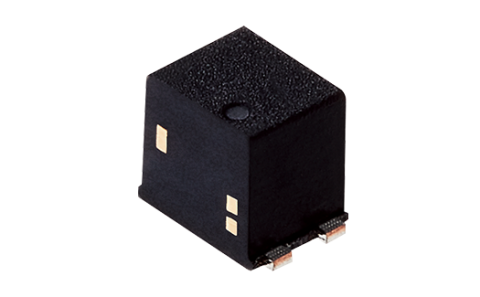
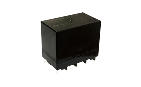
| Terminal Type | PC board terminal |
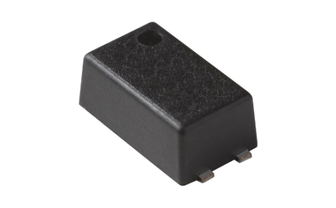
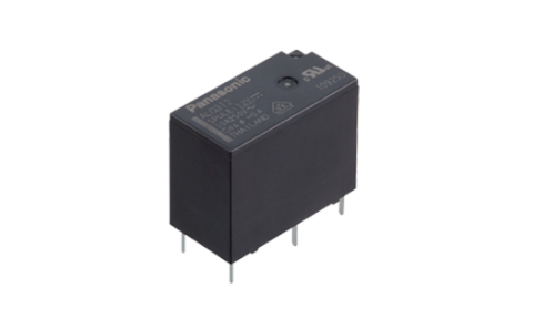
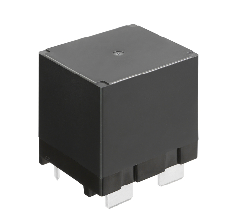
| Relay Shape | Slim type |
| Insulation Distance | [Between contact and coil] Clearance: Min. 5.29 mm, Creepage: Min. 5.35 mm |
| Accessories | Sockets are available. |
| Packing Quantity | Tube package |
| Packing Quantity; Inner Carton (Pcs.) | 25 |
| Packing Quantity; Outer Carton (Pcs.) | 1,000 |
| Operate Voltage (@20oC) | Max. 70% V of rated coil voltage (Initial) |
| Release Voltage (at20°C) | Min. 5% V of rated coil voltage (Initial) |
| Rated Operating Current [±10%] (at 20°C) | 4.6 mA |
| Resistance [±10%] (at 20°C) | 5,236 Ω |
| Rated Operating Power | 110 mW |
| Max. Allowable Voltage (at 20°C 68°F) | 120% V of rated coil voltage |
| Contact Resistance (Initial) | Max. 30 mΩ (by voltage drop 6 V DC 1 A) |
| Contact Rating (Resistive Load) | 5 A 250 V AC, 5 A 30 V DC |
| Max. Switching Power (Resistive Load) | 1,250 VA, 150 W |
| Contact Material | AgNi type + Au |
| Max. Switching Voltage | 250 V AC, 110 V DC (0.4 A) |
| Max. Switching Current | 5 A (AC, DC) |
| Min. Switching Load (Reference Value) | 100 μA 100 mV DC |
| Insulation Resistance (Initial) | Min. 1,000 MΩ (at 500 V DC, Measured portion is the same as the case of dielectric strength.) |
| Dielectric Strength (Initial): Between Open Contacts | 1,000 Vrms for 1 min (detection current: 10 mA) |
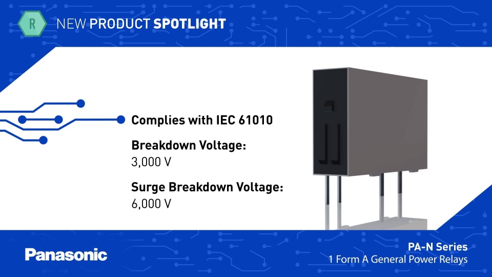
| Dielectric Strength (Initial): Between Contact and Coil | 3,000 Vrms for 1 min (detection current: 10 mA) |
| Surge Withstand Voltage (Initial): Between Contact and Coil | 6,000 V |
| Operate Time (Initial) (At 20oC) | Max. 10 ms at rated coil voltage (without bounce) |
| Release Time (Initial) (at 20°C) | Max. 5 ms at rated coil voltage (without bounce, without diode) |
| Hock Resistance (Functional) | 147 m/s2 (half-sine shock pulse: 11 ms, detection time: 10 μs) |
| Hock Resistance (Destructive) | 980 m/s2 (half-sine shock pulse: 6 ms) |
| Vibration Resistance (Functional) | 10 to 55 Hz (at double amplitude of 2.5 mm, detection time: 10 μs) |
| Vibration Resistance (Destructive) | 10 to 55 Hz (at double amplitude of 3.5 mm) |
| Conditions | Ambient temperature: -40 to +90℃ (Allowable temperature is from -40 to +60℃ at our standard packing condition.) Humidity: 5 to 85% RH (Avoid icing and condensation) |
| Mechanical Life | Min. 20x106 ope. (switching frequency: at 180 times/min) |
| Weight (Typ.) | Approx. 3 g |
| Resistive Load | [switching frequency: 20 times/min] Min. 100x103 ope. 3 A 250 V AC Min. 100x103 ope. 3 A 30 V DC [switching frequency: 6 times/min, ON : OFF = 1 s : 9 s] Min. 50x103 ope. 5 A 250 V AC [switching frequency: 20 times/min] Min. 50x103 ope. 5 A 30 V DC |
| Inductive Load | [switching frequency: 6 times/min, ON : OFF = 1 s : 9 s] Min. 100x103 ope. 2 A 250 V AC (cosΦ = 0.4) |
Stock check
APAN3124
What's New
Stay up to date

Latest Videos
Playlist

Why Should A Relay Meet The New NEMA 410 Standard? (S1 E1)

Smart Grid Products: LF-G Series Power Relays

Smart Grid Products: HE-V Series Power Relays
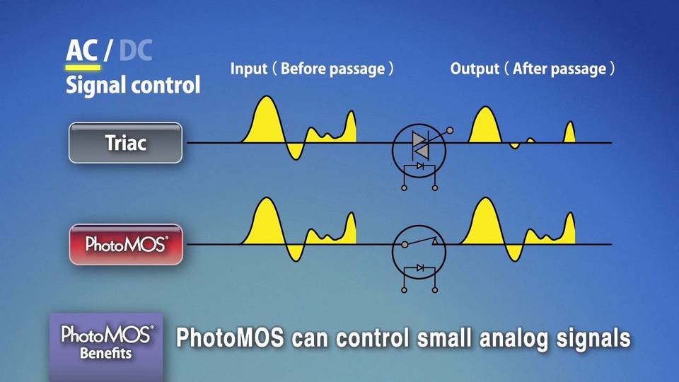
Features and Benefits of PhotoMOS®
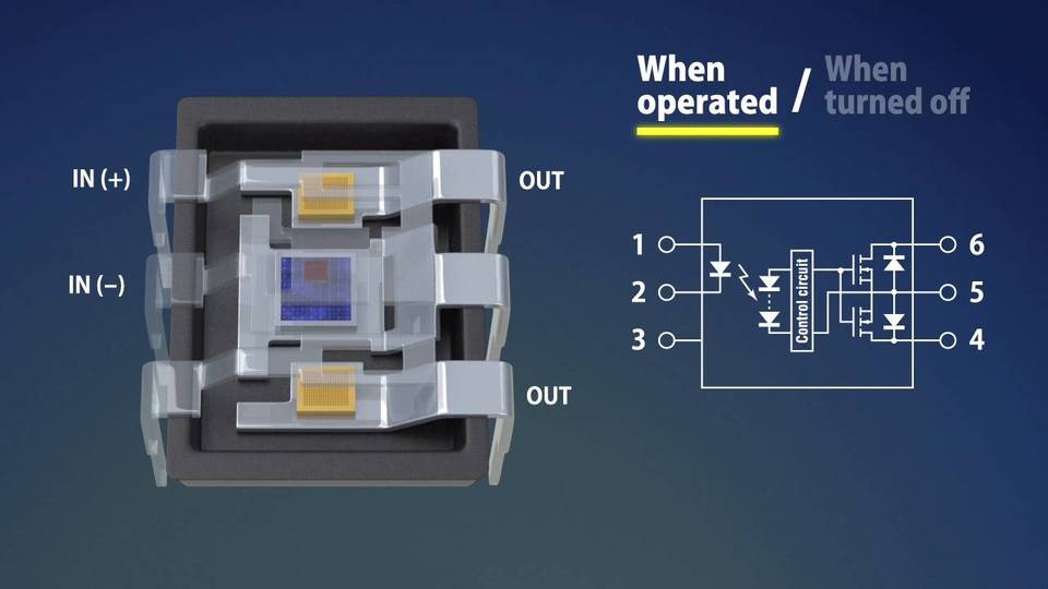
Introduction to PhotoMOS®

Where Technology Meets Humanity
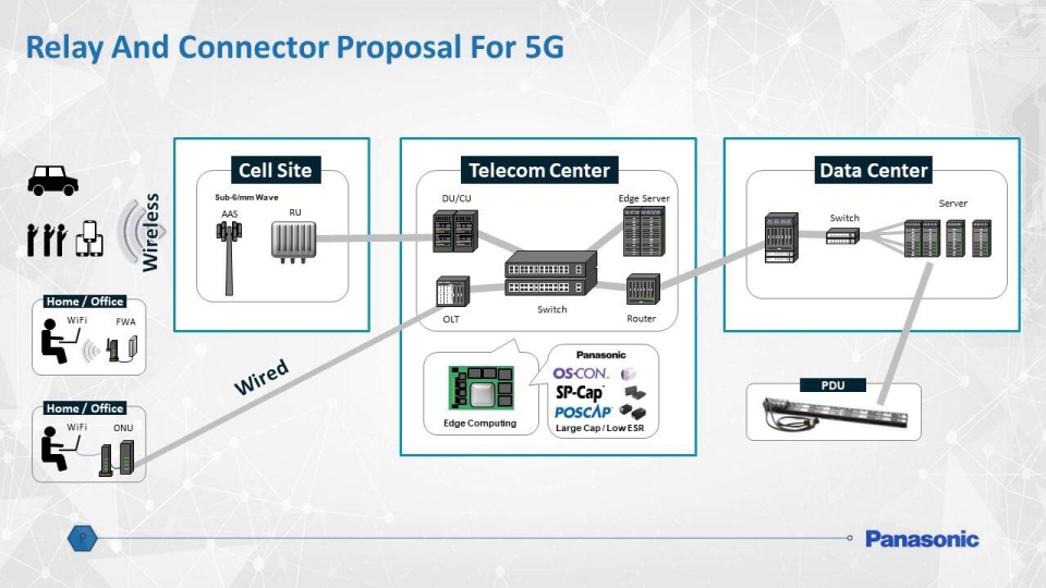
Panasonic Industrial Solutions for 5G Networking Applications
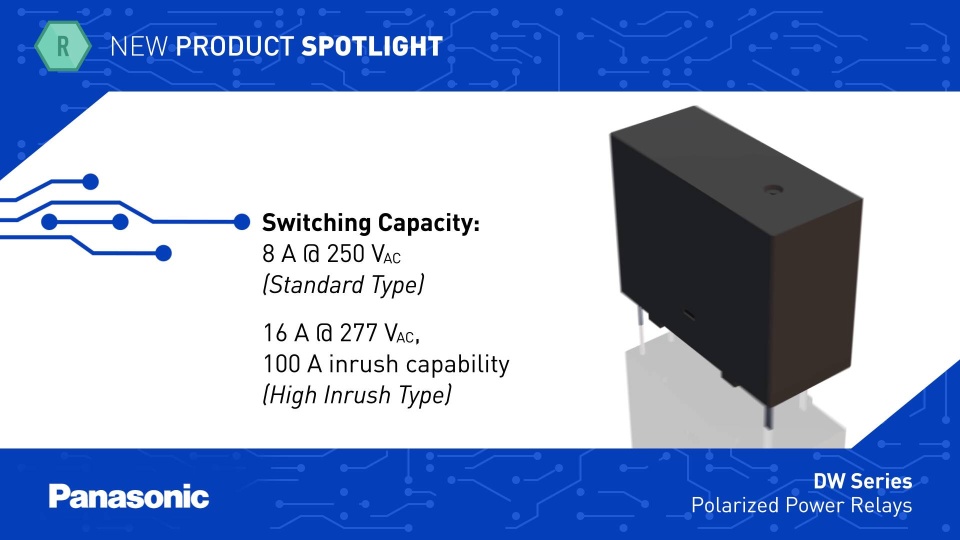
New Product Spotlight: DW Series Relays
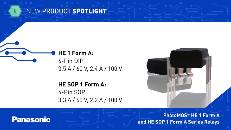
New Product Spotlight: PhotoMOS® HE 1 Form A and HE SOP 1 Form A Series Relays