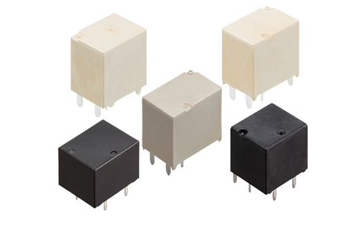
EB-N Series Relays

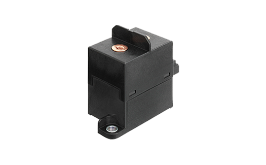
Panasonic's EB-N Series is a sealed Automotive Relay with a low profile (23mm height) and screw mount with copper tab terminals. The low profile allows the EB-N Series Relay to be mounted within battery cells so it can function as the battery disconnection protecting the Lithium-ion batteries during a malfunction. 

The EB-N Series Relay has a polarized double-make SPST (1FormA) contact arrangement capable of 100A @ 60VDC continuous current at 85 Degrees Celsius ambient temperature and can carry 300A for 5 seconds. The EB-N Relay can also cut-off 1,500A at 60VDC for 1 operation has a high switching capacity of 35A @ 14VDC for the Normally Open contact and 20A @ 14VDC for the Normally Closed contact.

Both sealed and flux-resistant construction types are available. A built-in resistor option is available for coil protection against EMF. Both 12V and 24V DC coils are available in this series.

Features and Benefits

  • 100A (85°C/38mm2) Nominal Current
  • Low Height (23mm) Enabled This Relay To Be Mounted Within Battery Cells
  • Max. 1,500A 60V DC Switching Off Possible

Applications

  • Electric Vehicles (48V Mild HEV)\
  • Main Relay Application To Protect Lithium-Ion Batteries
  • Battery disconnect application

Part Number List

Results 1
Models table for series EB-N Series Relays
Part No.DatasheetRated Coil VoltageContact ArrangementTerminal TypeCoil Terminal StructureTerminal StructureOperating Function Operate (Set) Voltage (at20&deg;C) (Initial) Release (Reset) voltage (at20&deg;C) (Initial)Rated Operating Current [&plusmn;10%] (at 20&deg;C)Coil Resistance (At 20oC)Rated Operating Power (at 20&deg;C) Max. applied voltageContact MaterialNominal Switching Capacity (Resistive Load) Max. Carring Current Min. Switching Load (Resistive) Contact Voltage Drop (Initial)Insulation Resistance (Min. M&Omega;)(Initial)Dielectric Strength (Between Open Contacts) (Initial)Dielectric Strength (Between Contacts and Coil) (Initial)Operate (Set) Time<br>(At Rated Coil Voltage) (At 20oC) (Initial)Release (Reset) Time<br>(at Rated Coil Voltage) (at 20&deg;C) (Initial)Shock Resistance: Functional Shock Resistance: DestructiveVibration Resistance: FunctionalVibration Resistance: DestructiveExpected Life: Mechanical LifeExpected Life: Electrical Life (Resistive)Expected Life: Switch-Off LifeExpected Life: Inrush Resistance Current<br>(Capacitor; 2000&micro;F)ConditionsWeight (Typ.)Inner Carton (Pieces)Outer Carton (Pieces) Usable Voltage Range
12V DC
1 Form A
Screw terminal
Lead wire
Cu without plating, with hole
Single side stable
Max. 9 V DC
Min. 0.5V DC
0.167 A
72Ω
2.0 W
16 V DC
Ag alloy
100A 60V DC (Carry, 38 mm2 wire)
100 A continuous / 300 A 5 sec. (38 mm2 wire) (Carry only)
1A 24 V DC (at 20°C)
Max. 0.02 V (by voltage drop 6 V DC 20 A)
Min. 100 MΩ (At 500 V DC, Measured portion is the same as the case of dielectric strength.)
1,500 V AC for 1min. (detection current: 10 mA)
2,000 V AC for 1min. (detection current: 10 mA)
Max. 50ms (without bounce)
Max. 30 ms (with no coil protective elements)
For ON: Min. 490 m/s2 (half-sine shock plus: 11 ms; detection time: 10µs)
For OFF: Min. 147 m/s2 (half-sine shock pulse: 11 ms; detection time: 10µs)
Min. 490 m/s2 (half-sine shock pulse: 6 ms)
10 to 200 Hz, 44.1m/s2 (detection time: 10 µs)
10 to 200 Hz, 44.1m/s2
(Time of vibration for each direction; X, Y, Z direction: 4 hours)
Min. 400,000 operations
(Swiching frequency: 0.5 s ON, 1 s OFF)
2 A 60 V DC Min. 50,000 operations
(Switching frequency: 5 s ON, 5 s OFF)
[Forward direction] 1,500 A 60 V DC, Min. 1 operation
[Reverse direction] 500 A 60 V DC, Min. 1 operation
150 A 6 V DC, Min. 100,000 operations
Switching frequency: 1 s ON, 2 s OFF
Ambient temperature: –40 to +85°C,
Humidity: 5 to 85% R.H. (Avoid icing when using at temperatures lower than 0°C.)
Approx. 140 g
50 pieces / 1 tray
50
10 V DC to 16 V DC

What's New

Stay up to date