Increasing Load Capacity in 6-Pin Type PhotoMOS® Relays
Published on- Relays & Contactors
PhotoMOS® Optically-Isolated Relays are quite different from standard electromechanical relays and have a variety of applications including test and measurement equipment, industrial control, and security. PhotoMOS Relays inherently have a limited DC load, however, by changing the output terminal connections, 6-Pin DIP and SOP type PhotoMOS Relays can withstand a higher load capacity. Using the Panasonic AQV2 Series PhotoMOS Relay as an example, this article will walk you through how to increase load capacity by slightly modifying your design’s output circuit.
The PhotoMOS Relay is composed of input pins that are connected to a light-emitting diode (LED) in the upper portion of the relay. When a current flows through the LED, it emits infrared light. Panasonic’s AQV2 PhotoMOS employs two MOSFETs to switch the output, which is connected to the source terminal (Pin 5). Figure 1 displays three output connections available for a DC load.
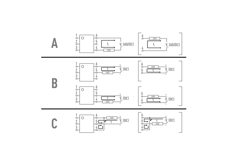
The controllable current increases from A to B to C. Configuration B provides a 15% increase in continuous DC load current, while configuration C pushes capability to a 100% increase over the A configuration.
So Why the Increase?
It’s not every day that you can double your DC load current with a little circuit trickery, but that’s exactly what you’re getting here. However, the 6-Pin PhotoMOS® models are unique in the fact that the source pin is exposed. This would not be possible in other models like the AQY, AQW, and AQS Series. By having access to the source pin, we can modify the total resistance value and, thus, change the controllable load current. Assuming that the on resistance value of one MOSFET is ‘R’, we can estimate the dissipated heat in the package for each electrical configuration as follows:
- Configuration A: (I2 x 2R)
- Configuration B: (I2 x R)
- Configuration C: (I2 x R/2)
As you can see, the total resistance value drops from A through C. This provides the increase in the controllable load current.
What About AC Loads?
It’s worth noting that the only configuration for an AC load that is possible is Configuration A. Configurations B and C are only possible with DC loads, so keep that in mind when designing your circuit.