How Panasonic’s Product Portfolio Serves e-Mobility
Published on- Capacitors
- Connectors
The Future of EVs and Electrified Transport
EVs initially made their major debut with the Tesla Roadster, Chevy Volt, and Nissan Leaf in the early 2010s — making waves within the automotive industry. Alongside this, talk of fully autonomous driving with Google driverless cars also started emerging using AI techniques. Now, over 10 years later, the electrified powertrain is quickly becoming commonplace in all major car and truck OEMs manufacturing EVs or hybrids (or both). Also commonplace are technical advancements in battery chemistries, power electronics, sensors, machine learning, and wireless communications for a next-generation driving experience. Just within the United States there are federal incentives to purchase/deploy these vehicles as well: From convenient “low-emission-vehicle” parking and EV charging stations in prime parking spots, to the tax incentives offered to individuals and companies alike (Figure 1). Public transportation is also going green, including metro buses, trolleys, and railways — all using much of the same underlying technology to achieve zero-emission mobility.
EVs are commonplace all over the globe today, with incentives at both the consumer and commercial level to encourage sustainability and shift from the reliance on diminishing resources.
All aspects of EVs rely on the integrity of their underlying components where, for instance, the power management systems must leverage high-performance and high-reliability parts to maximize power density and minimize the overall size of the solution.
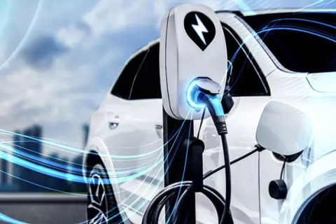
Figure 1: EVs are now common worldwide, supported by incentives for sustainability. Their performance hinges on reliable components for power management efficiency.
Selecting the Right DC Link and Filter Capacitors for Hybrids and EVs
Figure 2: Filter capacitors can either be used for noise elimination or signal smoothing.
As shown in Figure 2, the filter capacitor is often either used as the input or the output capacitor in automotive power converters to remove undesirable AC frequencies from the line. EMI filter and noise filter capacitors are used from the battery to DC/AC blocks. At the input, the filter capacitor will stabilize the input DC voltage and reduce any noise caused by ripple current. At the output, capacitors are used in the AC/DC block to smooth (filter) out the pulsating DC output after rectification to provide a regulated DC voltage to the load.
Input Capacitive Filters for High-Frequency Noise Reduction in EV Systems
Figure 3: Output smoothing hybrid aluminum electrolytic capacitors in 48V-to-12V DC/DC conversion for hybrid vehicles.
Smoothing capacitors are also used in DC/DC supplies and low-dropout (LDO) regulator outputs to minimize voltage changes that occur during load (battery) transients to create a constant output voltage (Figure 3). Other examples of output capacitor implementations in EVs and hybrids range from output smoothing in the DC/DC power supply for the automotive power control unit (PCU) and LED headlight circuitry.
Input capacitive filters should have a low ESR and high capacitance stability over temperature. A higher ESR will increase high-frequency noise across the capacitor. Capacitive filters used for higher frequencies (beyond 100 kHz) must generally have a low quality factor (Q) to more effectively filter out high-frequency noise and harmonics. Input filter capacitors can be used from the EV/hybrid battery to the battery management systems (BMS) and to provide stable input voltages to blower motors, ECUs, and millimeter-wave radar circuits for ADAS systems. Unlike DC link capacitors, filter capacitors do not necessarily require high capacitance and voltage ratings, but they must be able to sufficiently suppress AC pulsating current.
Hybrid vs. Aluminum Electrolytic
Since smoothing capacitors must handle large levels of current, aluminum electrolytic capacitors are often used where the effectiveness of the smoothing capacitor depends upon its capacitance value, working voltage, and maximum ripple current. However, the considerations that come with using aluminum electrolytics are their inherently high equivalent series resistance (ESR) causing higher resultant losses (more energy dissipated as heat) and ripple current, as the capacitor will be unable to sink and source the amount of current required.
Panasonic’s automotive-grade (AEC-Q200) hybrid capacitors leverage both the electrolytic solution technology and polymer technology for a high ripple-current-handling capability and high capacitance. As shown in Figure 4, the capacitors are optimized for a low ESR when compared to standard aluminum electrolytics, allowing these designs to benefit from the high electrostatic capacitance and working voltages of these devices without the downside of the relatively high ESR.

Figure 4: Panasonic's hybrid capacitors are optimized for a large current and low ESR that is relatively impervious to temperature variations.
Hybrid vs. MLCC
Figure 5 shows the impedance response of the ZC series hybrid capacitors compared to three paralleled off-the-shelf ceramic capacitors (MLCCs) used in smoothing capacitors in an LED power supply circuit. As shown in the image, the capacitors exhibit similar impedances while taking up the same amount of PCB space. The hybrid capacitor solution only uses a single capacitor, reducing the overall BOM cost and part count of the end-solution.
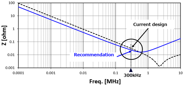
Figure 5: Impedance curve of smoothing capacitor solutions for an automotive LED power supply. The current design uses three MLCCs in parallel while the recommended solution leverages a single ZC series hybrid capacitor.
DC Link Capacitors
As shown in Figure 6, DC link capacitors form the intermediate stage between the DC source (i.e., the DC/DC converter or battery) and the DC/AC inverter that supplies the motor.
DC link capacitors are critical components for both EV and hybrid power conversion circuits such as oil pumps, electric power steering (EPS), belt-drive start generators (BSGs), electronic braking systems (EBS), blower motors, ADAS millimeter-wave radar, the DC/DC power supply for hybrids, and more. Selecting the right DC link and filter capacitors for an automotive design will boil down to performance, space, and cost optimization. In terms of performance, DC link capacitors must be optimized for capacitance density, voltage profile, ripple current, ESR, contact reliability, and high-temperature performance.
Panasonic’s ZE and ZF high-temperature series of hybrid capacitors are, for example, optimized for high ripple current up to 2 root mean square (RMS) current and a temperature guarantee up to 150o C for 1,000 hours. The ZT, ZS, ZU, ZUU, and ZTU series are specially designed to withstand large ripple currents on the order of 6.1 RMS at temperatures of 125o C (ZUU series). Combined with their inherently high capacitance, rated voltages, and low ESR, these capacitors effectively replace aluminum electrolytics while also saving board real estate and lowering BOM count/cost.
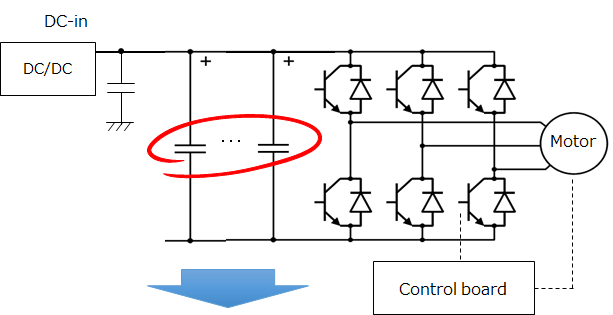
Figure 6: Basic DC link capacitor application circuit.
Film capacitors for applications beyond 80 V
It is important to note that these capacitors are designed for applications with working voltages ranging from 25 V to 80 V. The EZPV and ECWFP box-type film capacitors are well-suited for DC link and smoothing capacitor implementations in higher-voltage applications (up to 1,100 V). As shown in Figure 7, these use cases range from DC link capacitors in DC charging stations, main battery circuitry, and OBCs, to smoothing capacitors in electric compressors.
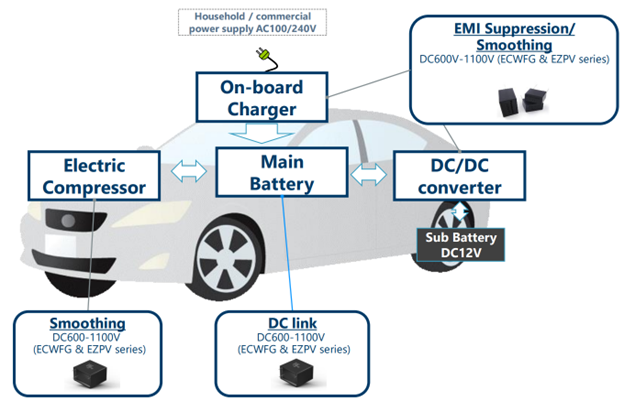
Figure 7: Applications for the Panasonic high-voltage box-type film capacitors: the ECWFG and EZPV.
Mounting and Vibration
As with many aluminum electrolytic capacitors, mounting can be an issue: These capacitors have many mechanical failure modes associated with vibration, including damage to the leads or damage to the rubber end seal causing electrolyte leakage. All electrified transport will experience extensive vibrational strain from the road and potential mechanical shock from various circumstances (e.g., off-roading, accidents). Typically, the ECU board-mounting process requires anti-vibration measures by anchoring large non-vibration-resistant components such as electrolytic capacitors. As shown in Figure 8, Panasonic’s hybrid capacitors have a built-in vibration resistance and have been tested to withstand an acceleration up to 30 G, thereby bypassing the use of adhesives and streamlining the production process.

Figure 8: The conventional surface-mount (SMD) electrolytic capacitor will have two terminal connections (left); newer SMD components will have an auxiliary terminal that drastically improves vibration resistance characteristics.
The Connected Backbone of EVs and Hybrids
Figure 9: The CF1 series of board-to-FPC automotive connectors.
Benefits of FPCs
Another critical aspect of modern vehicles are their connections: Newer vehicles are now outfitted with nearly 100 ECUs where each ECU handles its own share of specific signals, channels, and I/O types to control a range of complex automotive processes. The sheer density of signals calls for interconnects with high pin counts and smaller pitches to reduce the overall installation necessary and minimize any operator connection failures. Flexible printed cables (FPCs) such as the Panasonic CF1 and CF2 board-to-FPC solutions (Figure 9) have the conductors printed in the cable substrate, as opposed to conventional ribbon cables where the individual wires surrounded by an insulating material are deployed.
This allows for massive space and weight savings: Two factors that must be strongly considered in automotive designs given the density of wiring. Any marginal reduction in weight can extend the range of the vehicle per charge.
As shown in Figure 10, these FPC cables have the additional benefit of removing the need for wire harnesses between the FPC receptacles and the control board PCB’s receptacles where there is a direct connection between the FPC and board.
For these reasons, most in-vehicle module wiring, such as instrument panels, steering switches, rear lamps, shift levers, side mirrors, and headlamps, have become FPC-based. FPC connectors can also be used for critical systems such as the BMS, onboard chargers (OBCs), DC-DC converters, and LED-based head and rear lamp connections.
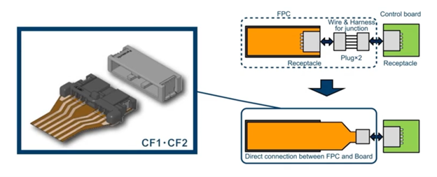
Figure 10: The direct connection between the FPC and PCB removes the need for additional wire harnessing.
Contact reliability and manufacturability
All wire harnesses must be able to withstand the temperature extremes and high-shock/-vibration environment of the automobile. Hybrid vehicles will have the additional vibrational and temperature strain from the heat coming off the ICE where ECUs mounted nearby must withstand the added stress. Panasonic’s FPC connectors offer a unique metal-to-metal, double-contact structure that ensures a high-contact reliability when experiencing vibrational strain. A heat resistance up to 125° C ensures the connectors can operate in harsh automotive environments. This diverges from the typical crimp contacts found in ribbon cables that require additional special equipment and are an avenue for corrosion to occur (e.g., fretting corrosion from vibration). It offers a degree of advantage of the conventional FPC contact with a direct FPC-to-metal transition that is easily impacted by vibration. This direct transition also calls for gold plating to reduce the contact resistance between the surfaces and remove corrosion concerns. A comparison of these different connector approaches can be seen in Figure 11.
As shown in the image, the connectors also benefit from a straightforward plug assembly where only one process is required without any special equipment for crimping or gold plating. This quality makes it easy for large-volume production of wire harnessing.
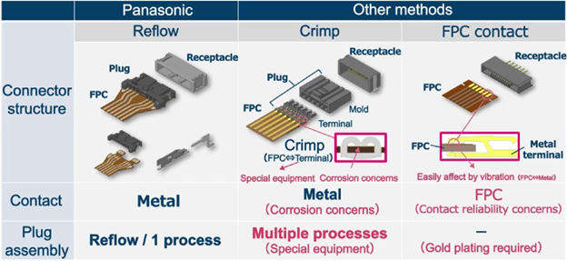
Figure 11: Comparison of the different flat, flexible cable methods for in-vehicle wiring.