Using PhotoMOS® to Replace Reed Relays
Published on- Relays & Contactors
The enhancement of electrical components is directly proportional to the growing need for higher-performing Semiconductor test equipment. As components become more diversified in their capabilities, production volumes increase and down-sizing occurs, the demand for higher functioning Relays is required.
Increasing Reliability by Changing Reed Relays to PhotoMOS®
Reed Relays including Mercury Reed Relays have dominated this market until the introduction of Solid-State devices. In the tester market, there is a growing trend to replace Reed Relays with PhotoMOS Relay solutions in order to increase long term performance and reliability. Furthermore, due to environmental impacts and regulations, Mercury type Reed Relays are required to be phased out and redesigned. Mechanical Reed Relays have been widely used in high-precision measurements due to their zero-leakage current, however, they require regular maintenance due to the wear and tear of their moving contacts. Such maintenance affects production capacity and overall production cost. Therefore, the demand for Solid State Relays have increased as a result. On the other hand, where Solid State Relays excel in reliability, the absence of a physical contact to provide isolation of the electrical signal causes leakage current.
In order to resolve this issue, Panasonic developed its “T-circuit” design to significantly reduce the leakage current. This solution uses three separate PhotoMOS Relays to create a circuit optimized for reducing leakage current and maximizing isolation at high frequency.
High Frequency Measurement Circuit & T-Circuit Schematic Using 3 PhotoMOS Relays
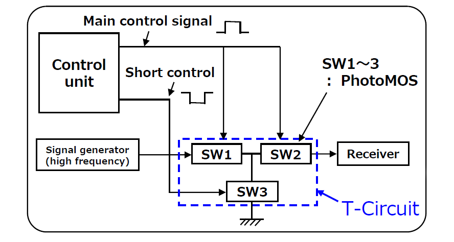
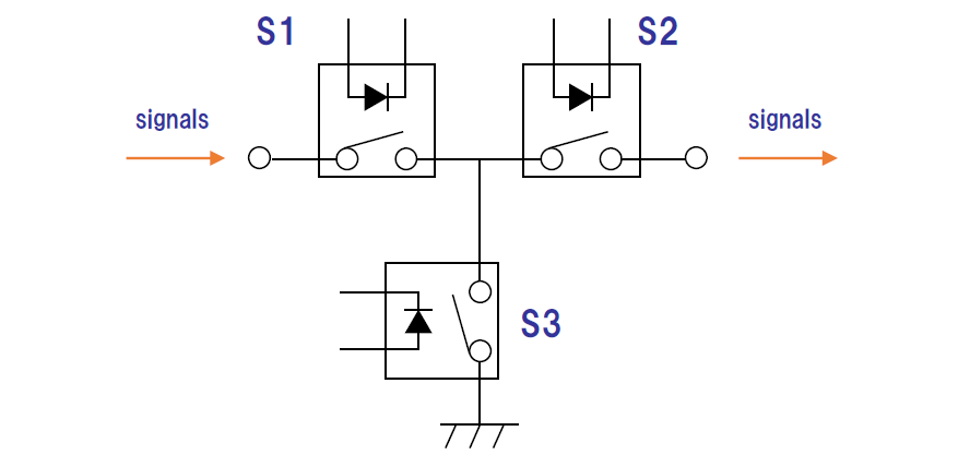
When the PhotoMOS is ON, two Relays with low on-resistance characteristics are used to pass the signal from input to output. This minimizes signal loss critical for taking small measurements. When the Output signal is turned off, the 2 PhotoMOS with low on-resistance will turn OFF while the third Relay which features a low output capacitance directs any remaining signal leakage to ground. Adopting this design allows for high-precision measurements, minimal leakage current, and maintenance-free devices.
T-Circuit ON & OFF State
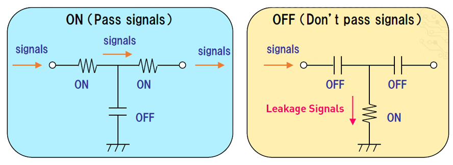
Left: T-Circuit ON State allowing the signal to pass with minimal losses
Right: T-Circuit OFF State isolating output and passing leakage to ground
One additional consideration to designing the T Circuit would be the ON/OFF timing which needs to be performed as a Break Before Make (BBM) switch. In order to do this successfully, the 2 low On-resistance PhotoMOS (SW1 and SW2) should be turned OFF before the low Output Capacitance PhotoMOS (SW3) is turned on. The reverse order should occur when turning off the signal as shown in the illustration below.
Make Before Break (MBB) Timing Circuit Waveform Timing