Three Methods For Reducing Coil Holding Voltage
Published on- Relays & Contactors
Panasonic’s Energy Management relays can be controlled in ways that help not only make products safer by generating less heat but also fewer allow for reduced power losses through lower coil holding techniques. Explore and discover some of the ways in which these relays can be controlled with less power using optimal circuit design methods.
In traditional non-polarized relay technology, nominal coil voltage must be continuously applied to the coil side to energize the relay which creates takes away from the system’s overall energy consumption efficiency. However, many of Panasonic’s newest relays, including LF-G, HE-S, HE Series PV type, and HE-V series relays, can be operated with reduced coil voltage so that lower power consumption can be achieved. A highly efficient electromagnet design and optimal spring structure allow these relays to provide energy savings. This is a major benefit to designs where power saving is very important for energy conscience applications.
Condition: Max. Contact Carrying Current (LF-G, HE, HE-S and HE-V)
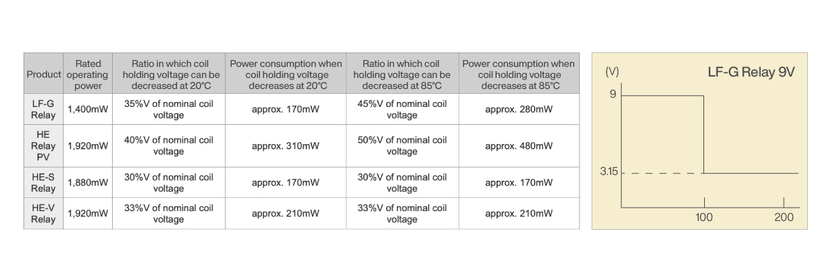
The table above explains reduced coil holding voltage that can be achieved after applying the rated coil voltage for 100ms or longer.
This feature of low coil holding voltage used to reduce coil holding power in AC load relays can be implemented in three common methods. While specifics to these methods are detailed below, each customer should always verify implementation in their actual circuitry.
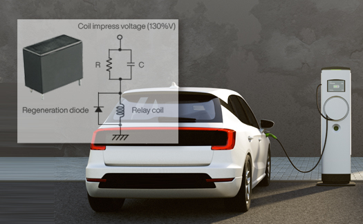
METHOD 1: CR CIRCUIT
Example of CR Circuit Method
1. Apply overrated coil voltage to the relay coil for 50ms or greater. This is typically around 130% of the nominal coil voltage.
2. Control power consumption when the relay is ON using relay coil resistance, C, and R.


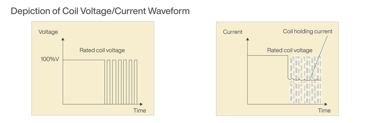
METHOD 2: PULSE WIDTH MODULATION (PWM)

Example of PWM Method
1. Turn MOS-FET ON to apply voltage to the relay coil for a minimum of 0.1s. Ensure MOS-FET is completely ON (Duty ratio 100%).
2. Start PWM control* with MOS-FET (Duty ratio 50%) to control power consumption when the relay is ON.
*Panasonic recommends a PWM control frequency of 20kHz to 100kHz.
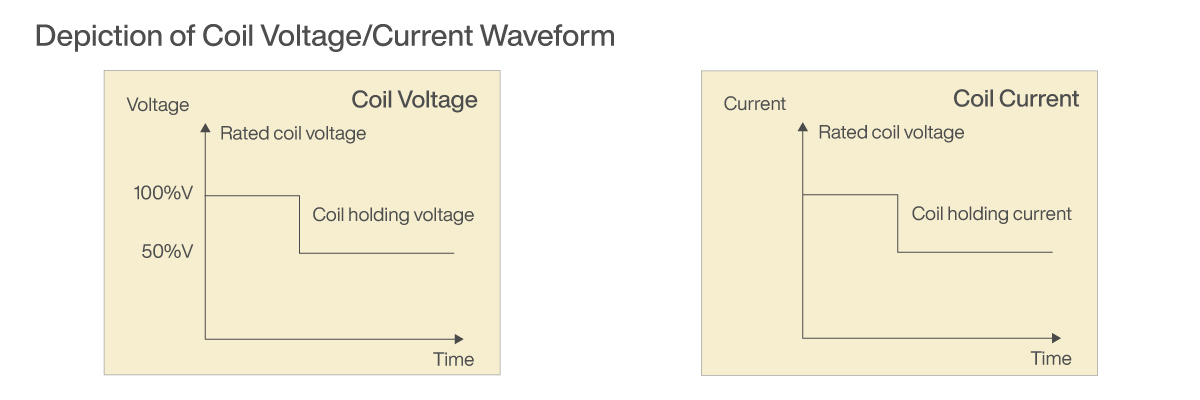
METHOD 3: SWITCH CIRCUIT
1. Operate by turning on SW1 and applying the rated voltage (100% of the nominal voltage) to the relay coil.
2. After at least 0.1 seconds delay after SW1 has been turned on, turn SW2 on and turn SW1 off again allowing the relay’s power consumption to be controlled by the value of resistance R.
*Set the coil holding voltage using resistance R, and the relay coil resistance to reach the voltage you are aiming for (around 50%V).

Relays with high switching capacity tend to be larger in size and have larger contact gaps which require a higher amount of power to maintain the energized state. Therefore, it is even more critical to reduce the amount of power needed to maintain the energized state. Following any of the above approaches will allow for power saving which can be very important for energy conscience applications such as Electric Vehicle Supply Equipment (EVSE), Photovoltaic Power Generation Systems, and other forms of power distribution.
Featured Relays for Reduced Coil Voltage
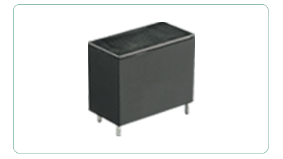
LF-G SERIES RELAYS
Panasonic's LF-G Series Relays are non-polarized 1 Form A power Relays that can switch up to 33 amps at 250 volts AC. These energy-saving relays feature high capacity control at 22A (standard) and 33A (high capacity), 250 VAC, and have a compact size that allows for smaller, higher-density designs.
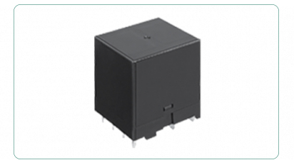
HE-S SERIES RELAYS
The HE-S Series is a compact Power Relay with low operating power and high-capacity switching. This relay features contacts with long electrical life and a high-capacity resistive switching load rating of 35A at 277VAC for 50,000 cycles. This relay also features a mirror contact structure (compliant with EN60947-4-1) which uses a 2 Form A coupled with a 1 Form B contact arrangement.
HE SERIES RELAYS PV TYPE
Panasonic's HE Series Relays PV Type is available in three different contact ratings: 35A, 48A, or 90A. These relays have a 1 Form A (SPST-NO) contact arrangement in a PC Board mountable small case size. The HE Series Relays feature the minimum contact gap and 2.5kW surge breakdown required by photovoltaic standard requirements
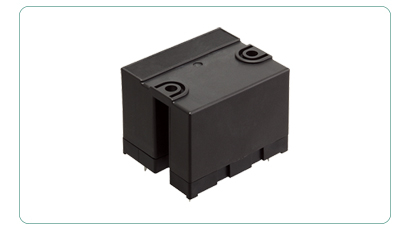
HE-V SERIES RELAYS
Panasonic's HE-V Series Relays are designed for usage within the solar, energy storage and inverter markets as a way to increase system efficiency as well as provide protection from highinrush currents. When these small sized RoHS Compliant relays are connected in series, two 1 form A contacts can cut off loads with a maximum switching capacity of 1000vdc, a 20A.